Havent heard any of you guys talk about this one so I guess no one has it.
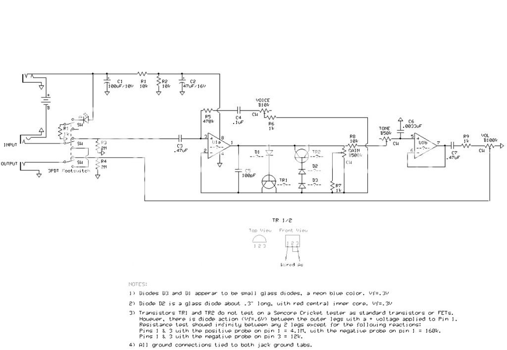
I do have the schematic but a few things are missing like the IC Chip values, transistor values, and diode values, although from the descriptions at the bottom, its pretty easy to tell that the diodes are germanium.
Ok, now its a .pdf file so I cant really upload it, but if someone gives me their email address that can upload it, I will send it to them to upload and post.
By the way, I did try breadboarding it without success. But thats could be from the wrong transistors used, wrong IC chip, wrong diodes, or just something that I didnt do right.
Kerry
Hermida Audio - Zendrive [ goop-alarm ] [traced]
-
call1800ksmyazz

- Breadboard Brother
- Attachments
-
-
call1800ksmyazz
- Breadboard Brother
^- aha! Never thought of that.
In that case...
Schematic: https://i14.photobucket.com/albums/a303 ... eSchem.jpg
PCB: https://i14.photobucket.com/albums/a303 ... ivePCB.jpg
Kerry
In that case...
Schematic: https://i14.photobucket.com/albums/a303 ... eSchem.jpg
PCB: https://i14.photobucket.com/albums/a303 ... ivePCB.jpg
Kerry
-
invictus

- Breadboard Brother
not really weird... seems like the internal diodes are used as clipping diodes in series with some other "glass" diodes mentioned. 1N64 maybe...
"im the master of my fate, im the captain of my soul... " -invictus
-
Dirk_Hendrik

- Old Solderhand
Information
Most likely yoy are right. R5 as a biasing diode to the junction of R1 and R2. The "voice' network as part of the feedback loop.kagaxdx wrote:Should R5 be conected to U1a pin 2 instead of 3?
Even that way U1a is still not biased.

Furtrermore those trasistors connected as diodes .
And supply power through a 10k resistor will not work that well.
-
Goop_buster

- Solder Soldier
The schematic is wrong and do not follow the PCB 
-
Goop_buster
- Solder Soldier
I made a quick try to bring order in this messjt wrote:If we delete the line that connects C2 to Pin 8,then connect positive side of C2 to the right side of R5 and connect Pin 8 to the positive side of C1 it must be OK.Am i right?
This (see below) is what is going on in the previous PCB at least. However there is some problems. The PCB has no place for a second diode in one of clipping directions. There is also no place for a resistor to the gainpot (as shown first schematic) so that may be placed off board ?? Feel free to make suggestions and/or corrections if there is anything wrong. I used MC1458, 1N34 and 2N7000 based on other hermida circuits.
-
invictus
- Breadboard Brother
this is assuming that the PCB layout is correct..
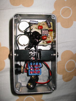
but what if the PCB is wrong? is there a gut shot of PCB solder side somewhere?
..
but what if the PCB is wrong?
..
"im the master of my fate, im the captain of my soul... " -invictus
-
Goop_buster
- Solder Soldier
Good pointinvictus wrote:this is assuming that the PCB layout is correct..
but what if the PCB is wrong?
..
Here is another gut shot but same goop there
http://www.digimart.net/images/64/DS00191845_3.jpg
-
call1800ksmyazz
- Breadboard Brother
I could always go knock on mr Hermida's door with schematic in hand 
He only lives 20-30 minutes from me. Actually, when I first started building pedals I met him in a local guitar shop (had no freakin idea who he was lmao). My parents were talking to him while I played guitar. If only I knew who he was and knew electronic stuff back then, I would have tried to impress him and try to work for him. Doh!
He only lives 20-30 minutes from me. Actually, when I first started building pedals I met him in a local guitar shop (had no freakin idea who he was lmao). My parents were talking to him while I played guitar. If only I knew who he was and knew electronic stuff back then, I would have tried to impress him and try to work for him. Doh!
The Mosferatu is a AMZ SoS-clone with a few altered values and MOSFETS instead of the diodes. The PCB for the Mosfertau and the part layout is the same on the ZD.
I think the only difference between those two is the clipping section and myabe a few part values.
JHS
I think the only difference between those two is the clipping section and myabe a few part values.
JHS
-
modman

- a d m i n
Information
- Posts: 4898
- Joined: 19 Jun 2007, 16:57
- Has thanked: 4411 times
- Been thanked: 2139 times
Jack Orman's Son of Screamer from a pirate site. I thought he would have put all his schematics online and understood that putting his designs online...JHS wrote:The Mosferatu is a AMZ SoS-clone with a few altered values and MOSFETS instead of the diodes. The PCB for the Mosfertau and the part layout is the same on the ZD.
I think the only difference between those two is the clipping section and myabe a few part values.
JHS
Please, support freestompboxes.org on Patreon for just 1 pcb per year! Or donate directly through PayPal