The Zendrive and the Mosferatu have the same PCB.
JHS
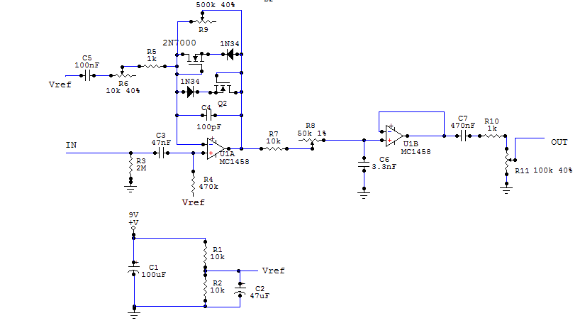
Hermida Audio - Zendrive [ goop-alarm ] [traced]
-
Goop_buster

- Solder Soldier
Thanks pf fan. Actually looking at the gut shots I suspect that one or two things are still missing in the schematic.
It must be the 1K resistor that is connected to the middle and one of the outer lugs of the gain pot as it can be seen in the schematic that call1800ksmyazz post at the begging of this thread.I think that nothing is missing in the pcb layout that he posted.
-
Goop_buster
- Solder Soldier
Thanksjt wrote:It must be the 1K resistor that is connected to the middle and one of the outer lugs of the gain pot as it can be seen in the schematic that call1800ksmyazz post at the begging of this thread.I think that nothing is missing in the pcb layout that he posted.
The reason it looks a bit different on the PCB compared to the gut shots may just be that the PCB layout is not a 100% copy of the original?
I see for instance three (standing) resistors in the upper right corner
http://fuzz.inrerocknroll.com/images/Zendrive3.jpg
Possibly they are just moved around bit to slightly different locations on this layout and the circuit is still a match.

Anyone have any idea what the op amp is? Is the MC1458 confirmed? I'd think you'd want something with a FET input as the second stage after the tone control.
I breadboarded one of these and am a bit disappointed in it. I've tried all sorts of op amps (TL072, TL082, RC4558, TL032, JRC4558, and others) and none of them really did a great job. It has a synthetic cardboardy tone in the lower mids, not much clarity or dynamics. Maybe the right op amp will make it shine.
I breadboarded one of these and am a bit disappointed in it. I've tried all sorts of op amps (TL072, TL082, RC4558, TL032, JRC4558, and others) and none of them really did a great job. It has a synthetic cardboardy tone in the lower mids, not much clarity or dynamics. Maybe the right op amp will make it shine.
-
briggs

- Tube Twister
Information
Try the LF353N - I've been enjoying it in SoS type circuit recently 

I am Klon.
-
briggs
- Tube Twister
Information
P.s Which schematic did you breadboard from?
I am Klon.
This one: https://i208.photobucket.com/albums/bb7 ... n_blur.gifbriggs wrote:P.s Which schematic did you breadboard from?
I used BSS98's or BS170's for the FET's, and low gain Ge transistors for the diodes (out of 1N34's). It wasn't bad, just not exceptional. Sounded kind of like a refined Tube Screamer, which is sort of is.
-
briggs
- Tube Twister
Information
Ah yes. Hmm, I used to build these all the time with those "voice" controls  I should have boxed them up and sold them for megabucks!
I've been working on my "Super SoS" design recently, looking at all of these boxes that use it as a building block for inspiration. It's got a control for bass cut, and a control for treble cut. I think I just need a "mid boost" control and I'm done
I've been working on my "Super SoS" design recently, looking at all of these boxes that use it as a building block for inspiration. It's got a control for bass cut, and a control for treble cut. I think I just need a "mid boost" control and I'm done
I am Klon.
Yeah, it might just be me, I don't really like the Tube Screamer topology that much (diodes in the first op amp feedback loop) for some reason; into a clean amp it just sounds a bit strange. But the OCD, ahem, modded VLOD has spoiled me forever perhaps. If someone made a "modded" VLOD that had all its clarity and dynamics but distorted smoothly (like a Dumble), I'd probably stop with the distortion boxes. If anyone knows of such a thing, please share the wealth.

Information
- Posts: 7
- Joined: 11 Sep 2007, 16:12
LF353N was already try. But not sound look like.
Last edited by guitarquiz on 08 Oct 2007, 15:26, edited 2 times in total.
Hi, I recently built ZD-Clone.
At first, I'm sorry for my bad ENGLISH.
Compare to real ZD (I sold last year), IMHO it sounds pretty close to the original, but a slightly less bass response.
I think 1458 chip is not bad, but JRC4558 is more better to me.
I don't know the schematic is correct or not.
Anyway,it is a nice Overdrive.
I appreciate members of this board.
Here is built report, but sorry Japanese only.
http://diystomp.ojaru.jp/sos.html
Thanks.
-
kusi

- Breadboard Brother
hi,
Kerry wrote about D1 & D3, they are "small blue glass diodes". i think, they are stadart-shottky diodes!
@Goop_buster; there is plenty of place under the goop for a secend diode in one direction. and i think kerry could count
excuse my english!
regards, ksui
Kerry wrote about D1 & D3, they are "small blue glass diodes". i think, they are stadart-shottky diodes!
@Goop_buster; there is plenty of place under the goop for a secend diode in one direction. and i think kerry could count
excuse my english!
regards, ksui
-
Goop_buster
- Solder Soldier
Hi Kusik**i wrote:hi,
Kerry wrote about D1 & D3, they are "small blue glass diodes". i think, they are stadart-shottky diodes!
@Goop_buster; there is plenty of place under the goop for a secend diode in one direction. and i think kerry could count
excuse my english!
regards, ksui
I think that you missunderstand a bit. I was not guessing what was under the goop or anything. All I did was an attempt at redrawing the schematic "a bit more clear" directly from Kerrys own PCB:
https://i14.photobucket.com/albums/a303 ... ivePCB.jpg
I could not see any more plausible diode than one in each direction there.
However, I have no problems with additional diodes in any direction if that is a more correct version
Best regards
Btw Regarding the MC.... Op amp in the schematic it was just a wild guess based on a previous Hermida circuit including that one. However any other OP amp is possible in this case.