"A bit ot but apparently Friedman has more stuff to come:
"
I see more peoples take on the board(s) were created. Because I had sooo many problems with this pedal, I just walked away from it for a long while. I may get back into it to figure out wtf was the problem now that the Summer is over and I have some time. I wonder if just upping the one cap as outlined pages ago would help?
I see there is the latest board that states no oscillation but looks like a hybrid as through-hole and SMD! I'm wondering why SMD at all and if you're going to do that, why not just create and EXACT clone, depopulate the pedal, and make a PCB from it and just post it. Then people would purchase the exact components and eliminate all of the osciallation and issues we had??
In regard to the top comment and link....it seems Friedman adds the MIDDLE pot to the Buxom and Shirley. I know Friedman's design are bascially exactly the same with small tweaks and the Middle pot was not included as a single pedal package was already maximized with 6 post, but think seeing how done in these other pedals and incorporating into the BE-100 with a larger enclosure would be a huge win!
My thoughts.
Friedman BE-OD Pedal [traced]
-
Frabbio

- Breadboard Brother
Upping the cap may reduce or eliminate the oscillation, but it will affect the tonal response of the pedal. Using short and shielded wires, especially on the input and the pots may help.rmroza wrote:" I wonder if just upping the one cap as outlined pages ago would help?
I see there is the latest board that states no oscillation but looks like a hybrid as through-hole and SMD! I'm wondering why SMD at all and if you're going to do that, why not just create and EXACT clone, depopulate the pedal, and make a PCB from it and just post it. Then people would purchase the exact components and eliminate all of the osciallation and issues we had??
My thoughts.
The layout uses smd IC because I have a lot of them, and SOIC-8 and SOT-23 are pretty easy to solder (i don't even turn on the hot air station for these packages).
I confirm that the layout is free of oscillation even with the gain control and gain trimmer maxed
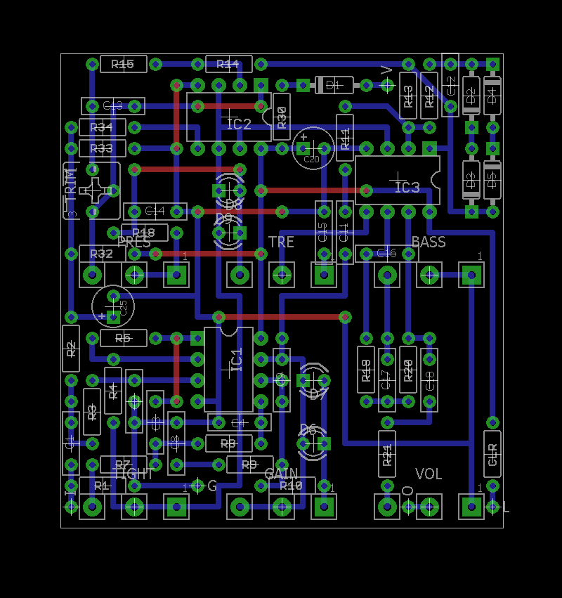
Here's mine. I drawn my own layout for 1590A encloser.
Clipping diode is BAV99 but I think nothing difference with 4 x 1N4148.
Change 120pF on feedback cap with 470pF. (for lower noise)
Clipping diode is BAV99 but I think nothing difference with 4 x 1N4148.
Change 120pF on feedback cap with 470pF. (for lower noise)
- Attachments
-
-
-
287m
- Breadboard Brother
finally, another 1590A Wizardpsychepool wrote:Here's mine. I drawn my own layout for 1590A encloser.
Clipping diode is BAV99 but I think nothing difference with 4 x 1N4148.
Change 120pF on feedback cap with 470pF. (for lower noise)
Awesome man!
-
roseblood11
- Tube Twister
Great!psychepool wrote:Here's mine. I drawn my own layout for 1590A encloser.
Clipping diode is BAV99 but I think nothing difference with 4 x 1N4148.
Change 120pF on feedback cap with 470pF. (for lower noise)
Please share the layout... Do you have any problems with noise or oscillation at higher gain settings?
Here's the layout. The reason that I didn't show my layout is there's many unpredictable cases.
I've been working on layouts to take into account the size of the parts, but in reality, there will be many challenges.
It is important to choose the size of the parts. I will give you some notes.
1. The film capacitors must have a lead spacing of 5mm.
2. The capacitors in pF should be chosen to be able to be mounted at 2.5mm intervals. (ceramic or monolithic would be good)
3. Electrolytic capacitors height must be 7mm or less.
4. If use the 8 pin / 14 pin exclusive IC socket, you can't install resistors under the IC socket.
So you must always cut out four or seven slots in a row and use them in two rows.
5. Wiring must be connected on the soldering side, not on the parts side.
6. Potentiometers must use 9mm size.
7. To secure the height to which the PCB is inserted and to insulate it, use a box jack as shown below and install as close as possible to the top of the case
Drilling guides are slightly different in size from case to case, so you will have to arrange them yourself by yourself.
It is not easy to make it, and it is difficult to make it more reliable than anything else.
You should be careful not to have shorts or disconnection.
Good luck to you.
I've been working on layouts to take into account the size of the parts, but in reality, there will be many challenges.
It is important to choose the size of the parts. I will give you some notes.
1. The film capacitors must have a lead spacing of 5mm.
2. The capacitors in pF should be chosen to be able to be mounted at 2.5mm intervals. (ceramic or monolithic would be good)
3. Electrolytic capacitors height must be 7mm or less.
4. If use the 8 pin / 14 pin exclusive IC socket, you can't install resistors under the IC socket.
So you must always cut out four or seven slots in a row and use them in two rows.
5. Wiring must be connected on the soldering side, not on the parts side.
6. Potentiometers must use 9mm size.
7. To secure the height to which the PCB is inserted and to insulate it, use a box jack as shown below and install as close as possible to the top of the case
- S20-1432P01WM.jpg (8.03 KiB) Viewed 3599 times
Drilling guides are slightly different in size from case to case, so you will have to arrange them yourself by yourself.
It is not easy to make it, and it is difficult to make it more reliable than anything else.
You should be careful not to have shorts or disconnection.
Good luck to you.
There is a little noise, but it's because of the amount of distortion.
The noise does not make you feel uncomfortable.
I know that the original pedal also has a lot of noise.
Perhaps if you use not such a complicated layout, it will have less noise. If so, no one will feel the image that this pedal is noisy.
The noise does not make you feel uncomfortable.
I know that the original pedal also has a lot of noise.
Perhaps if you use not such a complicated layout, it will have less noise. If so, no one will feel the image that this pedal is noisy.
-
287m
- Breadboard Brother
Now is answered 
psychepool layout is like my hero, miniaturization guru, the one and only, Sijosae
although mine perfboarder too, i almost never use 45 degree track, unless use thin leg
psychepool layout is like my hero, miniaturization guru, the one and only, Sijosae
although mine perfboarder too, i almost never use 45 degree track, unless use thin leg
Information
- Posts: 36
- Joined: 20 May 2009, 14:25
- Completed builds: Fuzz Face, Small Stone, Trem Lune, Fet Muff, Big Muff (green), Fuxx Face, Son of Screamer, Rat, Rebote 2.5, Opamp Big Muff, EA Tremolo, Easyvibe, Axis Face Si, Ross Compressor, Ross Distortion, DLS
- Location: Zagreb, Croatia
- Has thanked: 2 times
- Been thanked: 2 times
- Contact:
Built mine today:


Used 470pF instead of 120pF, and looks like I forgot to order the 10k rev Log pot for Presence, so I used 10k linear and it's still usable
Also, used 1N4148's as seen on photos, and TL082's instead of TL072, only had one TL072.
The protection diode is 1N4001 probably, I didn't have the other one that's noted in the original schem, it's just reverse polarity protection, it doesn't matter.
Only tried it with a small crappy solid state amp, but it sounds great, even through that I like how the treble and presence react to each other, and overall all the pots are quite useful, especially the "Tight" knob.
No oscillation, even with the trimpot fully clockwise, tight build for 1/4 resistors!
Now to find some letters to label it and that's it!
Used 470pF instead of 120pF, and looks like I forgot to order the 10k rev Log pot for Presence, so I used 10k linear and it's still usable
Also, used 1N4148's as seen on photos, and TL082's instead of TL072, only had one TL072.
The protection diode is 1N4001 probably, I didn't have the other one that's noted in the original schem, it's just reverse polarity protection, it doesn't matter.
Only tried it with a small crappy solid state amp, but it sounds great, even through that
No oscillation, even with the trimpot fully clockwise, tight build for 1/4 resistors!
Now to find some letters to label it and that's it!
If you scoop, it sounds like poop!
-
Ice-9

- Degoop Doctor
Information
Hi rmroza, I'm just wondering if you managed to get to the bottom of the problem you had with the 4 different builds you made of this pedal. It would be helpful to us all if you got it sorted.rmroza wrote:agung - Good to know and thanks for the feedback. How is the noise and squeal situation?!??
I've been busy with amps, but finished up yesterday, so will circle back around into seeing why all of the BE-OD clone (2-vero, 2-pcb) do not work!! People seems to be getting both variations done and the one common theme is "me", so I need to see what the fuck is up. I've built hundreds of pedals and never had problem(s) like this and nothing works. Components are correct and orientation and no apparent solder bridges. I'll try connecting the pots directly on and increasing the cap as many have suggested. Other than that, I'm out of options. It should work, but doesn't and some pots in reverse direction!
It's fairly straight forward, if you want to start it , press start. You can work out the rest of the controls for yourself !
No silicon heaven ? preposterous ! Where would all the calculators go ?
No silicon heaven ? preposterous ! Where would all the calculators go ?

-
bucksears
- Solder Soldier
Is there a link anywhere online?johnk wrote:i used a modified storyboardist one. it had to be modified to fit in a 125B.Nacho5 wrote:Which layout did you use?johnk wrote:i just finished one and it sounds great.
I'm working one out in Adobe Illustrator, but if there's something already available, I'd be keen to have a look.
-
287m
- Breadboard Brother
David Storyboardist layout --> http://effectslayouts.blogspot.co.id/20 ... be-od.htmlbucksears wrote:Is there a link anywhere online?johnk wrote:i used a modified storyboardist one. it had to be modified to fit in a 125B.
I'm working one out in Adobe Illustrator, but if there's something already available, I'd be keen to have a look.
===
For perfboarder like me, this pedal and dirty shirley is hard to get all onboard pots in 1590B
But, here the WIP while waiting pots and enclosure
-
bugg
- Breadboard Brother
http://www.pedalpcb.com/docs/Thermionic ... ion.v2.pdfballfire wrote:hey good day to every body..
i think im gonna build this overdrive ..may i know where i can find the right schematic of this pedal ??
thank you..
PedalPCB.com - http://www.pedalpcb.com/
Hey Bugg, may I ask what difference is between the 2 pcb versions? I just purchaced v1 with 1/8W resistors.bugg wrote:http://www.pedalpcb.com/docs/Thermionic ... ion.v2.pdfballfire wrote:hey good day to every body..
i think im gonna build this overdrive ..may i know where i can find the right schematic of this pedal ??
thank you..