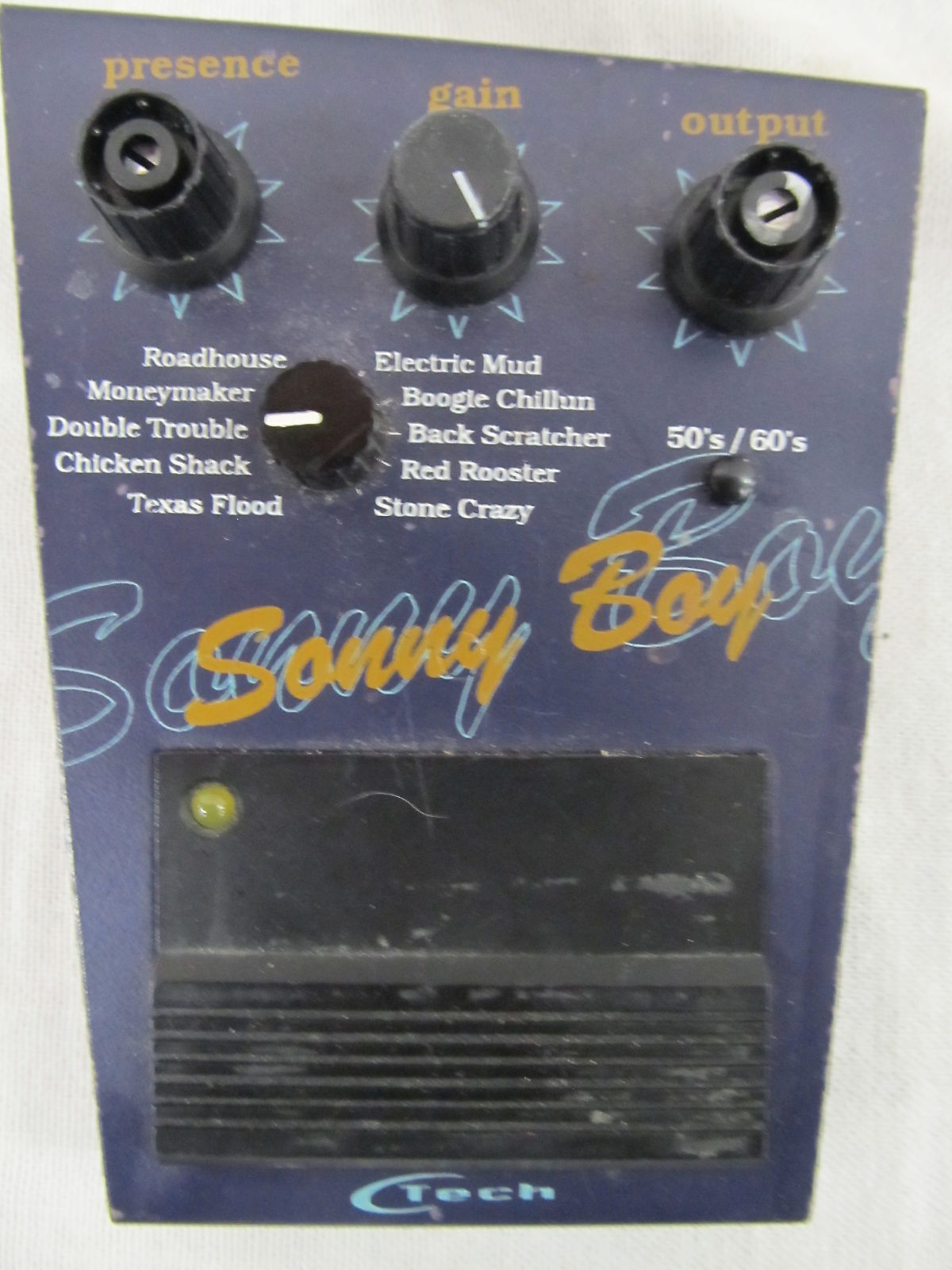
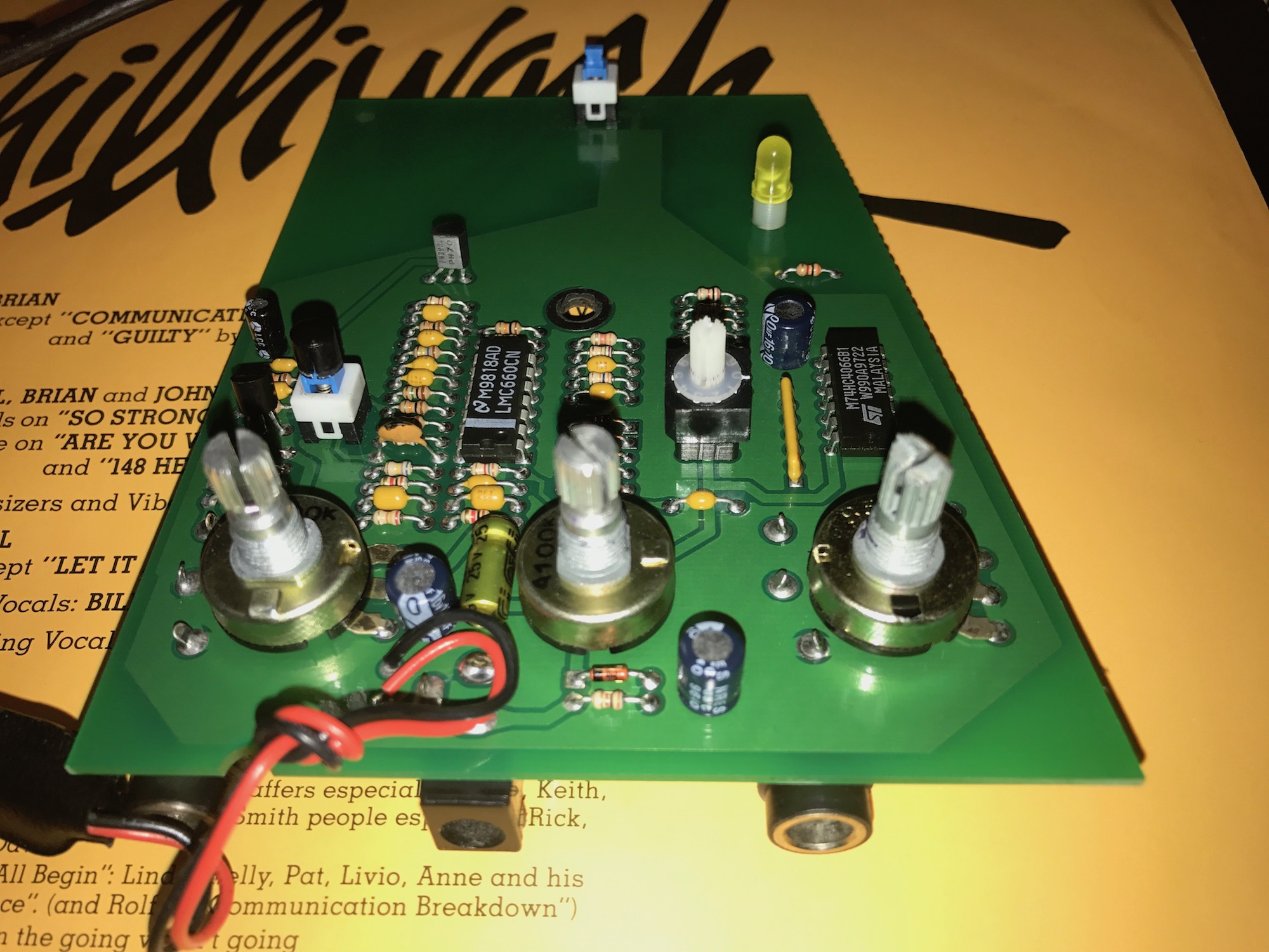
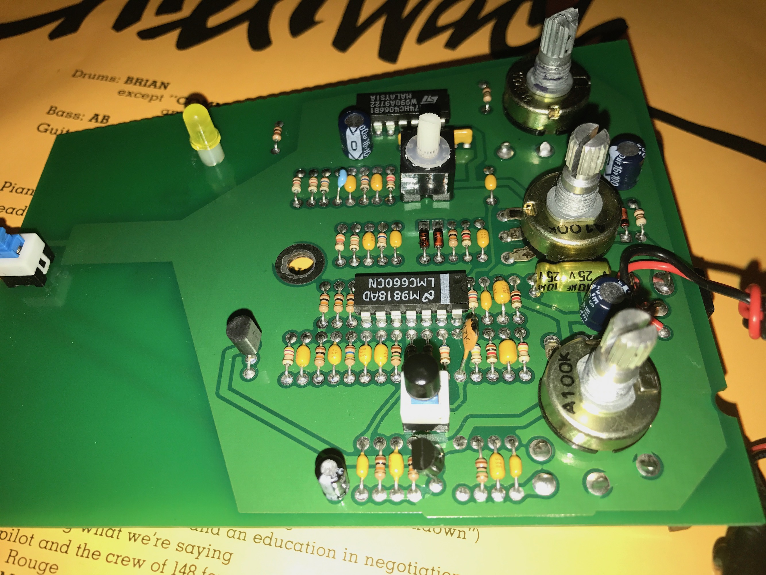
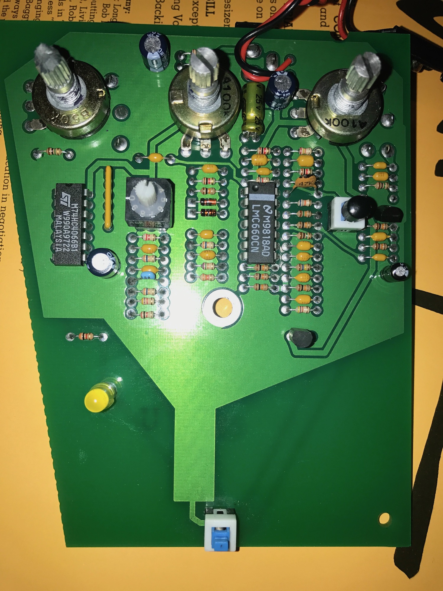
This is a strange one from the 90s. It appears to be a similar concept to the Sansamp Classic, using multiple op-amps and transistors to "model" amp sounds. Unlike the Sansamp the sounds are labeled by the songs they're supposed to be like. Since none of them are really clean, think of them as different flavors of overdrive/distortion. Unlike the Sansamp, also, they don't use a dip switch matrix, they use a switching IC controlled by a rotary knob to set the particular character of the overdrive. Lots of really nicely installed, TINY components in a weird trapezoidal box! (I shrank the files a bit, but didn't want to make them too hard to see. If you right click and "Display in another Tab" you can see them complete).
https://uwmadisonmedicalschool.box.com/ ... ecjc5n.jpg
https://uwmadisonmedicalschool.box.com/ ... aaoos4.jpg
https://uwmadisonmedicalschool.box.com/ ... y0rl32.jpg
https://uwmadisonmedicalschool.box.com/ ... vwqgs9.jpg
https://uwmadisonmedicalschool.box.com/ ... 22onkd.jpg
https://uwmadisonmedicalschool.box.com/ ... asxu6b.jpg
Anyway, if anyone is interested, have at it. I can help with values if they're hard to see, but I'm not much for the tracing thing!
Ctech - Sonny Boy
-
Belanger88

- Breadboard Brother
Definitely well built and the Semiconductors are of decent quality as well! Kemet, NSC and Mirco Electronics are some of my favourites , I think it could be a fun project for sure.
BJT or Fet?
BJT or Fet?
drbob1 wrote:This is a strange one from the 90s. It appears to be a similar concept to the Sansamp Classic, using multiple op-amps and transistors to "model" amp sounds. Unlike the Sansamp the sounds are labeled by the songs they're supposed to be like. Since none of them are really clean, think of them as different flavors of overdrive/distortion. Unlike the Sansamp, also, they don't use a dip switch matrix, they use a switching IC controlled by a rotary knob to set the particular character of the overdrive. Lots of really nicely installed, TINY components in a weird trapezoidal box! (I shrank the files a bit, but didn't want to make them too hard to see. If you right click and "Display in another Tab" you can see them complete).
https://uwmadisonmedicalschool.box.com/ ... ecjc5n.jpg
https://uwmadisonmedicalschool.box.com/ ... aaoos4.jpg
https://uwmadisonmedicalschool.box.com/ ... y0rl32.jpg
https://uwmadisonmedicalschool.box.com/ ... vwqgs9.jpg
https://uwmadisonmedicalschool.box.com/ ... 22onkd.jpg
https://uwmadisonmedicalschool.box.com/ ... asxu6b.jpg
Anyway, if anyone is interested, have at it. I can help with values if they're hard to see, but I'm not much for the tracing thing!
Success is no accident. It is hard work, perseverance, learning, studying, sacrifice and most of all, love of what you are doing or learning to do.
-
dv8r601
- Breadboard Brother
there's at least 1 philips 2N3904 below the lower right opamp (looking at front of board)(
, cant see the one on the side
, cant see the one on the side
-
dv8r601
- Breadboard Brother
That LMC660 looks really badass from looking at the data sheet:
http://www.ti.com/lit/ds/symlink/lmc660.pdf
CMOS Quad opamp
http://www.ti.com/lit/ds/symlink/lmc660.pdf
CMOS Quad opamp
-
bajaman

- Old Solderhand
Information
- Posts: 4549
- Joined: 26 Jun 2007, 21:18
- Location: New Brighton, Christchurch, NZ
- Has thanked: 596 times
- Been thanked: 2061 times
Also the diode values or codes
cheers
bajaman
be kind to all animals - especially human beings
-
Manfred
- Tube Twister
Information
- Posts: 1945
- Joined: 04 Apr 2009, 23:42
- Has thanked: 1675 times
- Been thanked: 1360 times
I have started to make a PCB-Clone.
Here the component side layout, but it may be helpful to fill in the missing values.
I cannot see the audio jack pin layout, any idea which type it could be?
Here the component side layout, but it may be helpful to fill in the missing values.
I cannot see the audio jack pin layout, any idea which type it could be?
-
bajaman
- Old Solderhand
Information
- Posts: 4549
- Joined: 26 Jun 2007, 21:18
- Location: New Brighton, Christchurch, NZ
- Has thanked: 596 times
- Been thanked: 2061 times
i have already done a clone for the board tooManfred wrote:I have started to make a PCB-Clone.
Here the component side layout, but it may be helpful to fill in the missing values.
I cannot see the audio jack pin layout, any idea which type it could be?
I am just waiting on drbob1 to confirm the capacitor and diode codes
cheers
bajaman
be kind to all animals - especially human beings
-
Manfred
- Tube Twister
Information
- Posts: 1945
- Joined: 04 Apr 2009, 23:42
- Has thanked: 1675 times
- Been thanked: 1360 times
Thanks Bajaman, in this regard it is not longer necessary from my side.i have already done a clone for the board too
-
Frank_NH
- Solder Soldier
This looks coolbajaman wrote: Here is a preliminary trace - just needs some capacitor values - or codes printed on them
Also the diode values or codes
cheers
bajaman
Bajaman - I think the rail for the IC non-inverting inputs should be at the middle of the 10K voltage divider (Vbias), with the 100uF cap in parallel to the lower 10K to ground? I'm also puzzled at how the switching works with this, but I guess I'll learn as the circuit trace evolves.
-
bajaman
- Old Solderhand
Information
- Posts: 4549
- Joined: 26 Jun 2007, 21:18
- Location: New Brighton, Christchurch, NZ
- Has thanked: 596 times
- Been thanked: 2061 times
No - the trace is correct - there are two 10k resistors as a voltage divider between +ve and ground, BUT there is a 10k resistor fed in series with the 100uf electrolytic from the midpoint of the divider. the three 10k resistors are immediately below the LMC660CN and the 100u electro is just to the right of the 4066 quad bilateral switch IC . the switching is achieved by connecting +ve voltage to one or more of the 4 control pins of the quad bilateral cmos switch via the 10 position rotary BDC encoder switch. Two of these switches control the gain of the second LMC6660CN opamp section and the other two switches control the post gain tone filtering and output level of this gain stage depending on which of the 10 preset sounds are selectedFrank_NH wrote:This looks coolbajaman wrote: Here is a preliminary trace - just needs some capacitor values - or codes printed on them
Also the diode values or codes
cheers
bajamanand something I would like to build on a vero layout.
Bajaman - I think the rail for the IC non-inverting inputs should be at the middle of the 10K voltage divider (Vbias), with the 100uF cap in parallel to the lower 10K to ground? I'm also puzzled at how the switching works with this, but I guess I'll learn as the circuit trace evolves.
cheers
bajaman
be kind to all animals - especially human beings
-
Frank_NH
- Solder Soldier
Thanks Bajaman. OK, I get it now - odd Vbias arrangement, but it apparently works - current draw must be low. I also understand the switching, and I suppose you could use 4 SPST switches if you didn't want the complication of the rotary switch.
-
bajaman
- Old Solderhand
Information
- Posts: 4549
- Joined: 26 Jun 2007, 21:18
- Location: New Brighton, Christchurch, NZ
- Has thanked: 596 times
- Been thanked: 2061 times
Yes the bias arrangement is unusual, but according to the data sheet the LMC660CN is designed to run from a single supply rail and is a pin for pin replacement for the LM324 (also designed for single supply operation) - perhaps the bias supply (which i would have thought unnecessary ) is designed to allow asymmetrical operation of the op amp gain stages  . In any case, i would not expect a device such as the TL074 to work correctly in this particular circuit configuration
yes - you could simply use four single pole switches in place of the rotary encoder switch - you could even leave out the 4066 cmos bilateral switch
I would certainly use a heavier duty footswitch, if I was building one of these
cheers
bajaman
yes - you could simply use four single pole switches in place of the rotary encoder switch - you could even leave out the 4066 cmos bilateral switch
I would certainly use a heavier duty footswitch, if I was building one of these
cheers
bajaman
be kind to all animals - especially human beings
-
bajaman
- Old Solderhand
Information
- Posts: 4549
- Joined: 26 Jun 2007, 21:18
- Location: New Brighton, Christchurch, NZ
- Has thanked: 596 times
- Been thanked: 2061 times
Hmmmm - while we anxiously await capacitor and diode codes, does anyone have a C-Tech Red Rooster pedal that they are willing to share gut shots and component values with us here
cheers
bajaman
cheers
bajaman
be kind to all animals - especially human beings
-
Frank_NH
- Solder Soldier
Looks like the Red Rooster was the Rock version of the Sonny Boy...drbob1 wrote:Promise I'll get to the cap values!
I've never even heard of the Red Rooster! I wonder how many of those they made?
http://www.effectsdatabase.com/model/ct ... r#pictures
-
drbob1
- Cap Cooler
Yeah, knowing it existed and ever having seen one are very different. There's none for sale, no links except for one review on Harmony Central from years ago. It's kind of a ghost!
Anyway, here's the best I can do with the components. A couple of problems came up:
1. No markings I can see on the small caps, at all
2. The slightly larger mustard colored caps each have 4 markings on them: 2 codes of 3 letters and 2 codes of 3 numbers. Anyway, I captured all I could see. With these old eyes, though, it's a little iffy if they're perfect!
3. Transistors I think I got fine, but I couldn't read a blessed thing off the diodes
4. Corrected a few components-a cap marked as a resistor, a diode marked as a resistor, and one extra cap that wasn't there
To get a better read on things, I suspect you'd have to take it apart, and I know I'm not capable of neat enough soldering to put it back together properly. I guess if someone wants to do it badly enough I could send it to them, but that isn't super exciting to me...
-
bajaman
- Old Solderhand
Information
- Posts: 4549
- Joined: 26 Jun 2007, 21:18
- Location: New Brighton, Christchurch, NZ
- Has thanked: 596 times
- Been thanked: 2061 times
some of those capacitor numbers are strange - 735? 744?
Anyway thanks to drbob1's diligence, we now have the switch BCD encoder deciphered and here are my best guesses so far for capacitor and diode values based on simulations - i have a pcb ready to roll that will fit in a Hammond or similar 1590BB enclosure - buffered or true bypass with a second footswitch to engage the 50s/60s boost. Cast your eyes over this latest schematic and let me know your thoughts
cheers
bajaman
be kind to all animals - especially human beings
drbob1 just led me to this post and forum. I just picked up one of these today, and I love the sounds, but cannot use it (live) as is.
Does anyone see the possibility of a multi-footswitch option in place of the rotary?
1 footswitch 50s/60s boost
1 on/off
presence/gain/volume knobs as existing
10 footswitches to select existing presets
Does anyone see the possibility of a multi-footswitch option in place of the rotary?
1 footswitch 50s/60s boost
1 on/off
presence/gain/volume knobs as existing
10 footswitches to select existing presets
-
The Rotagilla

- Diode Debunker
Not that this helps, but I used to live about 10 minutes away from where they were made. It's been years since I've played one but I want to say I remember it being decent.
The television will not be revolutionized.