It's probably just because I use the wrong nomenclature for lugs, I just went with 3 - hot, 2 - wiper, 1 - ground when I started making pedals and it's stuck now unfortunately.Seishin wrote:I should keep it shut. For some reason I thought you were talking about my layout. :p Treble bleed is on the hot and wiper lugs.Lawnchair wrote:No disrespect intended. But as sure as the sky is blue it's lugs 2&3. Please see Mikes Vero layout and my drawing. the top lug grounds through r8.Seishin wrote:Dude treble bleed should be on lugs 1 & 2!!! If you are talking about the picture on my blog you gotta flip it in yr head to visualize it properly!Lawnchair wrote:HEADS UP!!
If you built your own DLS the instructions for the mod should be lugs 2&3 of the gain pot. Same as the 47p cap.
On Nics site the two lugs identified in the pic are lugs 2 & 3 not 1 & 2. The pic is correct, just not the lug #s
Catalinbread - Dirty Little Secret [traced]
-
ShortScaleMike

- Resistor Ronker
Information
-
Lawnchair

- Solder Soldier
3- hot, 2 -wiper, 1 -ground That's how I read them too. Always have. My appologies if this is in contrast to the accepted norm.ShortScaleMike wrote:It's probably just because I use the wrong nomenclature for lugs, I just went with 3 - hot, 2 - wiper, 1 - ground when I started making pedals and it's stuck now unfortunately.Seishin wrote:I should keep it shut. For some reason I thought you were talking about my layout. :p Treble bleed is on the hot and wiper lugs.Lawnchair wrote:No disrespect intended. But as sure as the sky is blue it's lugs 2&3. Please see Mikes Vero layout and my drawing. the top lug grounds through r8.Seishin wrote:Dude treble bleed should be on lugs 1 & 2!!! If you are talking about the picture on my blog you gotta flip it in yr head to visualize it properly!Lawnchair wrote:HEADS UP!!
If you built your own DLS the instructions for the mod should be lugs 2&3 of the gain pot. Same as the 47p cap.
On Nics site the two lugs identified in the pic are lugs 2 & 3 not 1 & 2. The pic is correct, just not the lug #s
No apologies! I made up the way I reference the lugs too. :pLawnchair wrote:3- hot, 2 -wiper, 1 -ground That's how I read them too. Always have. My appologies if this is in contrast to the accepted norm.ShortScaleMike wrote:It's probably just because I use the wrong nomenclature for lugs, I just went with 3 - hot, 2 - wiper, 1 - ground when I started making pedals and it's stuck now unfortunately.Seishin wrote:I should keep it shut. For some reason I thought you were talking about my layout. :p Treble bleed is on the hot and wiper lugs.Lawnchair wrote:No disrespect intended. But as sure as the sky is blue it's lugs 2&3. Please see Mikes Vero layout and my drawing. the top lug grounds through r8.Seishin wrote:Dude treble bleed should be on lugs 1 & 2!!! If you are talking about the picture on my blog you gotta flip it in yr head to visualize it properly!Lawnchair wrote:HEADS UP!!
If you built your own DLS the instructions for the mod should be lugs 2&3 of the gain pot. Same as the 47p cap.
On Nics site the two lugs identified in the pic are lugs 2 & 3 not 1 & 2. The pic is correct, just not the lug #s
-
Lawnchair
- Solder Soldier
Heads up!
I was starting a DLS Double Deluxe Vero build today. Two is better than one. I've been experimenting all week.
In the first minutes I'm noticing a few possible errors in the Vero layout.
1) C-10 (part # on Catalinbread board) is missing. You'll notice on my original drawing of the circuit there is a 100p cap between G2 & G3 on the board. The 47p cap is on the pot lugs.
2) C3 and C4 in the Vero layout are backwards and should be conected at the Anode.
3) look at the original sketch from the DLS board C3 and C4 junction at the source of Q1 (Q2 on vero) with the undertrace. I don't see that in the Vero layout.
I'm looking at the rest now.
-
WhiteKeyHole
- Cap Cooler
I missed that note about the 47pF capacitor directly on the gain potentiometer, do you think it's significant enough to warrant an update (to the part list)?
Ok, one last thing before I go to bed... In looking at the Vero, C3 (anode) connects to the Pole of Sw1 and C4 to Sw1a. In your scheme, it's the other way around - the 4.7uf (C4) is on the pole of Sw1. Is that correct? I'm too tired to swap those now, so I'll try it tomorrow if this may be what's causing my issue.
I think it's worth a mention, but to my ears, it's not essential. Of course, my pedal isn't 100% 'right' yet so YMMVWhiteKeyHole wrote:I missed that note about the 47pF capacitor directly on the gain potentiometer, do you think it's significant enough to warrant an update (to the part list)?
-
ShortScaleMike
- Resistor Ronker
Information
We lost some discussion and progress during the crash of the site, so here is the v4 vero with some fixes.
Any more that I have missed?

Any more that I have missed?
-
madbean
Information
Built mine up tonight. Sounds badass. Great design and killer tones are to be had! I noticed a 4k7 from lug 1 to ground on the tone pot made the sweep a little more even and not so extreme on the filtered end.
Guess I better get to drilling an enclosure.
Guess I better get to drilling an enclosure.
-
ShortScaleMike
- Resistor Ronker
Information
Surely if you want to make it smaller you should just start from scratch with your own paper design and layout?roseblood11 wrote:Mike, could you please post the *.diy file? I wanna try to make this a little bit smaller ...
I have uploaded it but I don't think it is a particularly lardy layout, it is actually pretty compact.
http://www.mediafire.com/?unmtmwmow3i
-
roseblood11
- Tube Twister
I just wanna shrink it to 22 or 23 columns to make it fit into a Hammond B...
And as I don´t have much time at the moment, I wanna do it quick and dirty by stacking some components.
It´s gonna be ugly and unreadable
regards, Immo
-
ShortScaleMike
- Resistor Ronker
Information
Try taking the Rawk/Rock switch caps off the board and mount them to the switch.
Also some of the tone control connections such as the R15/C15 to ground could be done on the pot etc.
Also some of the tone control connections such as the R15/C15 to ground could be done on the pot etc.
-
RnFR
- Old Solderhand
Information
bad schems deleted, parts list amended. ![[smilie=a_wizard.gif]](./images/smilies/a_wizard.gif "a_wizard")
"You've converted me to Cubic thinking. Where do I sign up for the newsletter? I need to learn more about how I can break free from ONEism Death Math." - Soulsonic
Blog-APOCALYPSE AUDIO
Blog-APOCALYPSE AUDIO
-
frequencycentral
- Cap Cooler
+1, one of the neatest vero layouts I've seen.ShortScaleMike wrote:.........but I don't think it is a particularly lardy layout, it is actually pretty compact.
-
ShortScaleMike
- Resistor Ronker
Information
Thanks man, I love the work of yours I've seen particularly your riff on the Clairi(not).
-
roseblood11
- Tube Twister
Hi,
has anyone tried different boosters in front of the DLS?
I think of adding a booster and a second switch because I think it would be useful to switch from rhythm to lead sound.
The SHO is my favorite, because it´s a small and simple circuit, but I wonder if there´s another booster that works better with the DLS? Maybe the Keeley Java Boost that´s used in one of the Soundclips?
-
fosnal1950
- Breadboard Brother
I believe a rangemaster was recommended in front.
Today I experimented some more with my 4 tranny DLS ( or adapted MU amp) and changed the source resistor for Q 4 to half its size : there's a 2.7 K in the schematic which actually measures 1.5 K in circuit and paralelled it with another 2.7 K so this brings it down to 1 K which gives more gain and I like it much better now.
You can't see it in the pic because it was on a switch at the time )
( Bringing down the Q1 resistor was something I didn't like so much).
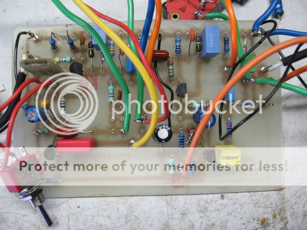
So If you like to build my version , experiment with the source resistors.
I also changed the output cap ( electrolyte) of 2.7 uF to a filmcap of 1 uF.
Alf
Today I experimented some more with my 4 tranny DLS ( or adapted MU amp) and changed the source resistor for Q 4 to half its size : there's a 2.7 K in the schematic which actually measures 1.5 K in circuit and paralelled it with another 2.7 K so this brings it down to 1 K which gives more gain and I like it much better now.
You can't see it in the pic because it was on a switch at the time )
( Bringing down the Q1 resistor was something I didn't like so much).
So If you like to build my version , experiment with the source resistors.
I also changed the output cap ( electrolyte) of 2.7 uF to a filmcap of 1 uF.
Alf