You're wonderful, John! If you want, after you will trace it, we can try to make a tradejohnk wrote:well, since no one has replied, I just bought another one for analysis. it should be here next week so hopefully I can get to the bottom of what the problem with the posted schematic is.
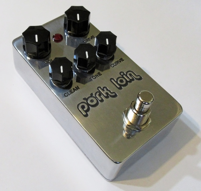
Way Huge - Pork Loin [traced]
-
gigelmargel

- Resistor Ronker
-
johnk
- Resistor Ronker
okay, the original arrived and I found all of the issues with the schematic and IvIark's vero. YAY!!!!
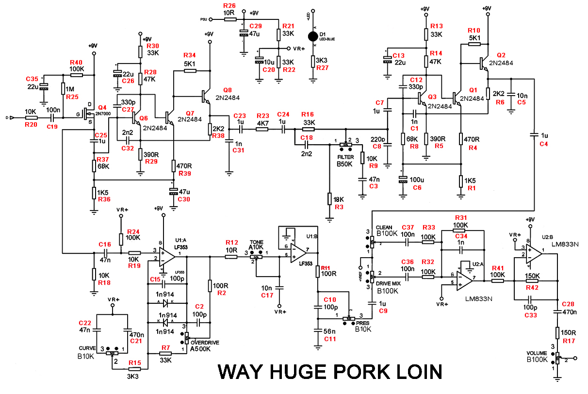
here's a copy of the schematic with all of the correct values and with the 'voice' trimpot removed (just like in the original:
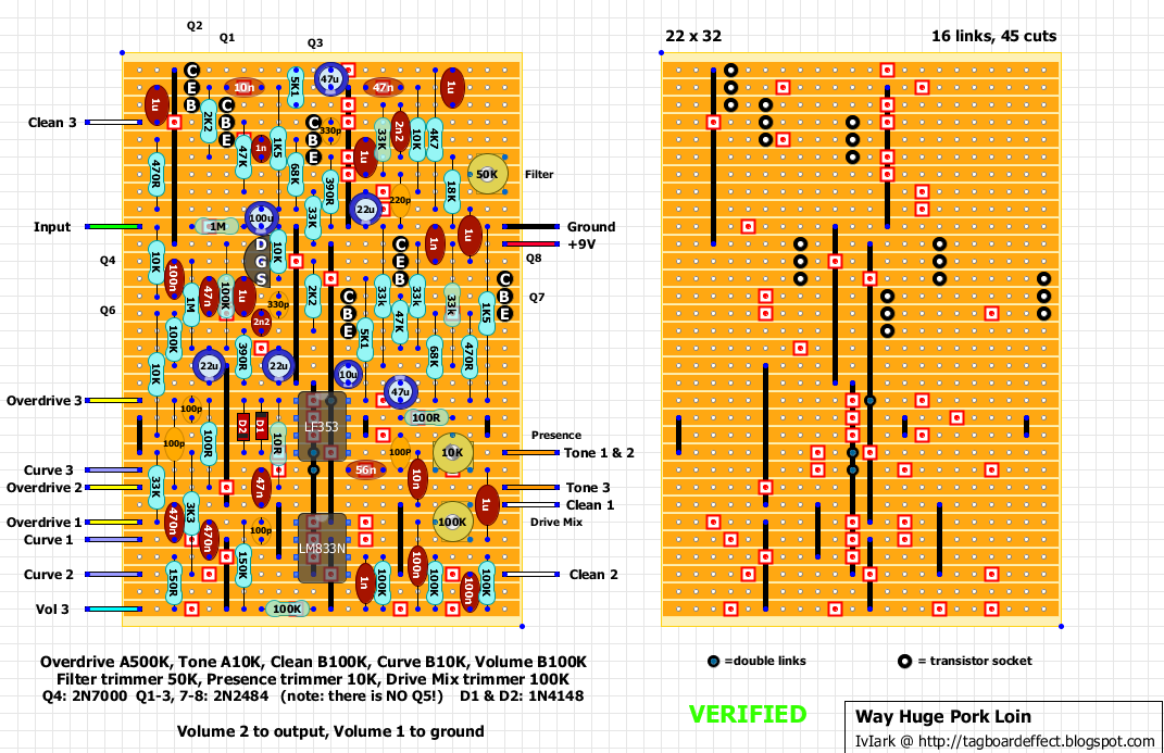
and here's IvIark's corrected and verified vero of it:
here's a copy of the schematic with all of the correct values and with the 'voice' trimpot removed (just like in the original:
and here's IvIark's corrected and verified vero of it:

-
jalmonsalmon

- Solder Soldier
Very nice! Good work!johnk wrote:I used a brother p-touch labeler.Intripped wrote:very nice pedal!
...those WHITE LETTERING, pliz explain: how you do it?
May I ask what you use for the top coat over the P-Touch Labeler?
-
LaceSensor
- Cap Cooler
That's a legit looking clone
Nice work everyone
Nice work everyone
-
GodSaveMetal
- Resistor Ronker
early.memoirs wrote:PL has a lower clipping level, much lower gain though.
i find the curve control really muddied up the sound, you have to blend the clean stage in about 1:1 to get it a bit clear.
havent had a chance to build that board. since it utilizes 9mm pot which actually hard to find hereearly.memoirs wrote: Had just finished a double sided layout for 1590B enclosure if anyone interested (a bit cramp). I haven't build it myself. Maybe in a week or two.
so i made a second attempt on my layout. the goal is to fit it in 1590bb, utilizing board mounted pots + toggle switch. lot of jumpers to keep it single-sided.
here's the composite. report back soon along with the project file.
Please post alll!!! BOM, PCB layout one sided PCB please!!! thanks I stay tunned!!
I just finished* building this using IvIark's vero layout. I had (and am having) some trouble with the 1uF caps. I used big honkin' metal film box caps in 2 places where I could physically fit them. Then I figured out that if I socketed the remaining 1uF box caps, that raised them up enough to clear nearby components, so I could fit the rest that way. And that worked just great, until I tried to close the 1590BB.  There isn't enough clearance with the pots+plastic dust covers+doublesided tape+PCB+socket+bigass box cap. I even removed the doublesided tape (it wasn't sticking to the plastic pot dust covers anyway; anybody got any tips for that??), and the caps still wouldn't fit.
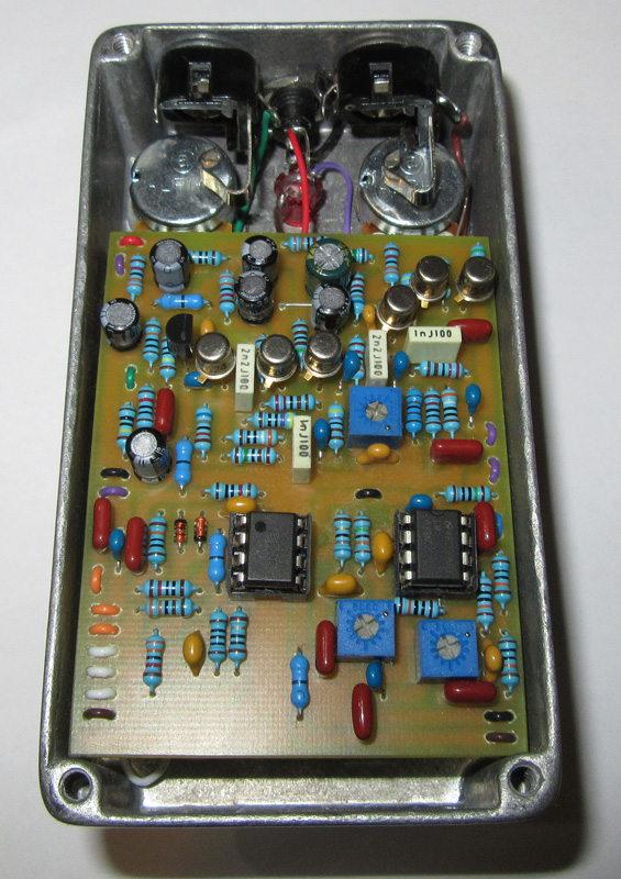
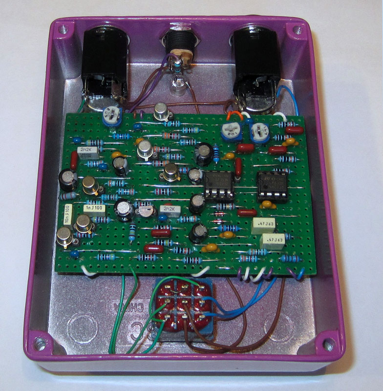
I came back to this thread for johnk's photos, and it looks like those yellow-orange 1uF caps are tantalums (at least they look exactly like the handful of tantalums I have). I've never actually used tantalums before; I just ordered some as soon as I had trouble cramming the box caps in. Do the tantalums work/sound ok here, and if so, can someone help me out with polarity? Whenever I've seen electrolytics in the audio path, they've almost always been oriented with positive on the input side, negative on the output side. Is it that straight-forward?
Am I correct in thinking that all these 1uF caps in the Pork Loin are functioning as coupling capacitors? I just read that tantalums "should be avoided in audio coupling (bipolar) circuits" (AMZ's cap FAQ) -- does this apply here?
Sorry for cramming so many questions into one post. Thanks to anyone who has the patience to read and answer at least some of these.
* sort of finished
Hello! If you were going to put a Send/Return insert point to splice before the Clean section of the Pork Loin (maybe a Swollen Pickle, for example), at what point in that schematic would it be best to patch it in? Ideally I'm looking to use a heavier drive pedal before the Clean preamp section, and still have the overdrive section in parallel. Hope this makes sense, thanks very much to everyone for this thread!
In an attempt to contribute since I have found great info in this threads.
I recently bought a 2nd pork loin to run a stereo rig (long story). I was surprised that the newer pedal was noticeably brighter. I walked the circuit and found that
Capacitor C34 has been updated to a value of 220 pF
It makes the pedal brighter and is worth the try for those that find the original too dark. Cheers and heads off to tripps for my all time favorite od pedal.
-
gigelmargel
- Resistor Ronker
Anyone has a PCB for Pork Loin?
Thank you!
Thank you!
-
modman

- a d m i n
Information
- Posts: 4898
- Joined: 19 Jun 2007, 16:57
- Has thanked: 4411 times
- Been thanked: 2139 times
- Attachments
-
- Pork Loin Guts
- way-huge-pork-lion-guts__30359.1517614862.jpg (31.6 KiB) Viewed 12331 times
Please, support freestompboxes.org on Patreon for just 1 pcb per year! Or donate directly through PayPal
-
x-tn

- Breadboard Brother
See the (incorrect) schematic on page 2:FeVeR2112 wrote:Does anyone know what the omitted voice pot was or how it affected the circuit? The schematic here doesn't include it so can't see where it was fitted in.
https://www.freestompboxes.org/viewtopic ... 20#p170819