Chunk Systems - Agent 00FUNK! [traced]
-
pedalgrinder

- Cap Cooler
I will pray to the pedal gods most profusely for you!!! May your solder flow well and behold a pedal for before you! Now go young jedi use the pedal force.
What's the best thing about fat chicks and scooters? There both fun to ride around until your mates find out!
-
Bernardduur

- Transistor Tuner
Nice! It is a shame I don't have the pedal anymore (I had it for a test so only limited time)........hellinoo wrote:Ok I have a schematic written on paper. I used the original schematic and traced the unit only with the pictures provided. The original schematic appears to be correct. Except for small changes in the values of resistors (I'm not sure because of the bad quality pictures). Especialy R4,R10,R6,R9. I've might have missed something so I'm going to double chceck it. I'm also using schematics of other effects as some sort of guidline. When I'll tripple chceck the schematic, I'm gonna try it on a testboard. If it works I'll build it and post vertified schematics and layouts here (+ some optional mods of mine that came to my mind today). Wish me luck. I'm gonna need it.
I also found these two pictures. Helped me a lot.
FRONT
BACK
'No more....... loud music.......'
Follow my love for pedals and amps on https://bernardduur.blogspot.com and https://www.instagram.com/bernardduur1
Follow my love for pedals and amps on https://bernardduur.blogspot.com and https://www.instagram.com/bernardduur1
-
chicago_mike

- Tube Twister
Did I post these already???
- Attachments
-
 A00F_hires.pdf
- (1.28 MiB) Downloaded 322 times
-
- A00F2-checkplot-2.pdf
- (77.53 KiB) Downloaded 237 times
-
- A00F2-1.pdf
- (26.54 KiB) Downloaded 285 times
Skyline FX 2013
-
chicago_mike
- Tube Twister
Anybody brave enough to try a layout? 
Skyline FX 2013
-
Nocentelli

- Tube Twister
Information
- Posts: 2222
- Joined: 09 Apr 2009, 07:06
- Location: Leeds, UK
- Has thanked: 1155 times
- Been thanked: 954 times
MkI or mk2?
modman wrote: ↑ Let's hope it's not a hit, because soldering up the same pedal everyday, is a sad life. It's that same ole devilish double bind again...
-
chicago_mike
- Tube Twister
either or 
Skyline FX 2013
-
lietuvis

- Breadboard Brother
definitely, will try, to fit 1590b, fairly simple circuit as well as brown dog, could be both in same enclosure.chicago_mike wrote:Anybody brave enough to try a layout?
-
chicago_mike
- Tube Twister
Both in one enclosure would be cool. Make the "side chain" thing a footswitch option.
Skyline FX 2013
-
Nocentelli
- Tube Twister
Information
- Posts: 2222
- Joined: 09 Apr 2009, 07:06
- Location: Leeds, UK
- Has thanked: 1155 times
- Been thanked: 954 times
I'm going to breadboard this tonight, but i have no 3v zeners. I have other values, maybe 5v1. I've seen plenty of OTA filters of this type, but i've not come across this variation with what looks like a bias voltage applied to pin 1+16, so i'm not sure if it could be kludged with a straight voltage divider, say 6k8 instead of the zener?
modman wrote: ↑ Let's hope it's not a hit, because soldering up the same pedal everyday, is a sad life. It's that same ole devilish double bind again...
-
chicago_mike
- Tube Twister
Its a real nice sounding filter pedal.
Skyline FX 2013
-
Nocentelli
- Tube Twister
Information
- Posts: 2222
- Joined: 09 Apr 2009, 07:06
- Location: Leeds, UK
- Has thanked: 1155 times
- Been thanked: 954 times
Demo's sound good, but they're all with bass: I'm building this for guitar but i do like a nice resonant LPF sweeping the low frequencies, so i'm sure it will work ok. If it works out on the breadboard, i'll do a vero layout, probably replacing the trigger input with a send/return loop like the Meatball. Thanks again for the schematics.
modman wrote: ↑ Let's hope it's not a hit, because soldering up the same pedal everyday, is a sad life. It's that same ole devilish double bind again...
-
chicago_mike
- Tube Twister
Happy to help!
Skyline FX 2013
-
karul
- Cap Cooler
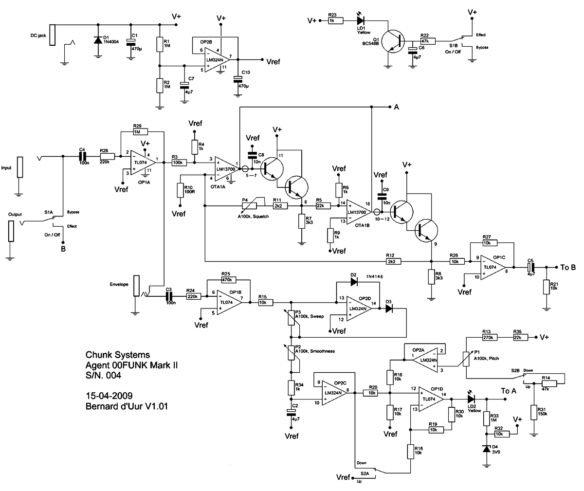
There are few minor errors in Bernard d'Uur's schematic for Mark II (thanks to chicago_mike):
R24 is 100k - should be 220k
(part number errors)
R29 should be R25
R30 should be R7
C81 should be C9
P1 should be P4 - squelch pot
version 1.01
R24 is 100k - should be 220k
(part number errors)
R29 should be R25
R30 should be R7
C81 should be C9
P1 should be P4 - squelch pot
version 1.01
- Attachments
-
-
- chunksystem-1.jpg (80.87 KiB) Viewed 2655 times
-
johnk
- Resistor Ronker
I used Bernard's schematic and added the chip's pinout numbers so I could more easily draw up a PCB with diy layout creator.
I then etched a PCB for it, and built it but it's not working yet. I've tested it and scoped pretty extensively, it but something is definitely not right.
here's his schemo with the chip #'s:
and here's my layout:
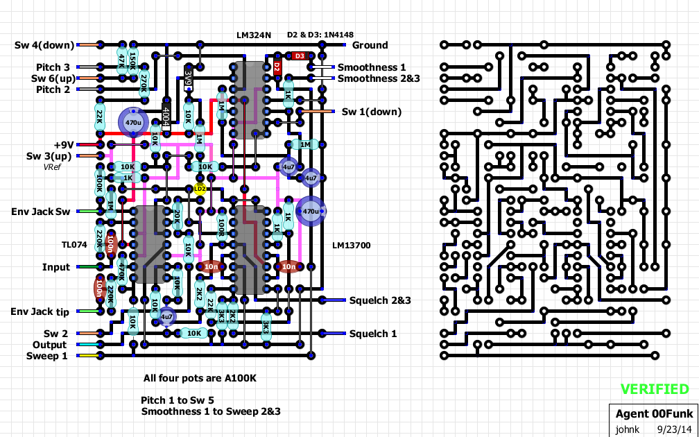
if anyone can see any errors on the schemo or my layout and help me with this, it will be greatly appreciated, since i'd like to pair this envelope pedal with the Brown Dog that I recently built.
I then etched a PCB for it, and built it but it's not working yet. I've tested it and scoped pretty extensively, it but something is definitely not right.
here's his schemo with the chip #'s:
and here's my layout:
if anyone can see any errors on the schemo or my layout and help me with this, it will be greatly appreciated, since i'd like to pair this envelope pedal with the Brown Dog that I recently built.
-
chicago_mike
- Tube Twister
- Attachments
-
- f3b77a25051a2a5d092bcdcd1fdce5dfe90f34078a95bdce6f051751f4803fed[1].jpg (28.66 KiB) Viewed 2595 times
Skyline FX 2013
-
chicago_mike
- Tube Twister
John, do you have the origional factory schematic and other files?
Skyline FX 2013
-
johnk
- Resistor Ronker
I scoped mine and tried a bunch of stuff but to no avail.
Bernard's schematic shows pins 3, 5 & 10 on the TL074 going to vref, as well as pin 5 on the LM324N, whereas Mike's shows all of those pins going to ground so the power supply is wired differently in the two posted schematics.
Bernard's schematic shows pins 3, 5 & 10 on the TL074 going to vref, as well as pin 5 on the LM324N, whereas Mike's shows all of those pins going to ground so the power supply is wired differently in the two posted schematics.
-
karul
- Cap Cooler
they are the same, take a better look at the power section of Mike's schematic:johnk wrote:I scoped mine and tried a bunch of stuff but to no avail.
Bernard's schematic shows pins 3, 5 & 10 on the TL074 going to vref, as well as pin 5 on the LM324N, whereas Mike's shows all of those pins going to ground so the power supply is wired differently in the two posted schematics.
GND is marked as V-, and virtual ground as GND
- Attachments
-