Mad Professor - Deep Blue Delay [traced]
-
rocklander

- Old Solderhand
Information
- Posts: 2726
- Joined: 18 Apr 2008, 11:33
- my favorite amplifier: my jansen bassman 50
- Completed builds: rebote 2.5; supreaux; odie; heartthrob tremolo; ross phaser; dr. boogey; thor; baja black toast; slow gear attack, rebote, tri-vibe, small clone, little angel, magnus modulus, echo base, hex fuzz, big muff, 22/7.
- Location: Rotorua, New Zealand
- Has thanked: 1406 times
- Been thanked: 231 times
- Contact:
glad someone has found it useful.. I've not noticed a vol drop, but I'm a few weeks away from integrating it into my new 1590a board (waiting on some rt angle phono plugs) so can't offer a full comparison sorry

world's greatest tautologist ...in the world
Ronsonic wrote:...the lower the stakes the more vicious the combat.
atreidesheir wrote:He should be punched in the vagina.
-
rasta_maleek

- Resistor Ronker
Wow, a really tiny pcb, I like a lot little things.rocklander wrote:and here's my build
certainly not a project for beginners; plenty of places where the tracks shorted out when soldering and had to reaaaallly pay attention to that and remove some snot, and scrape the screwdriver through a few spots. great feeling getting it going, but tricky finneky crap to get the bits soldered in.
recommendation from me is to use monolithic multilayer caps rather than anything else. I squeezed in some mylar ones in there, but box caps would have no show.
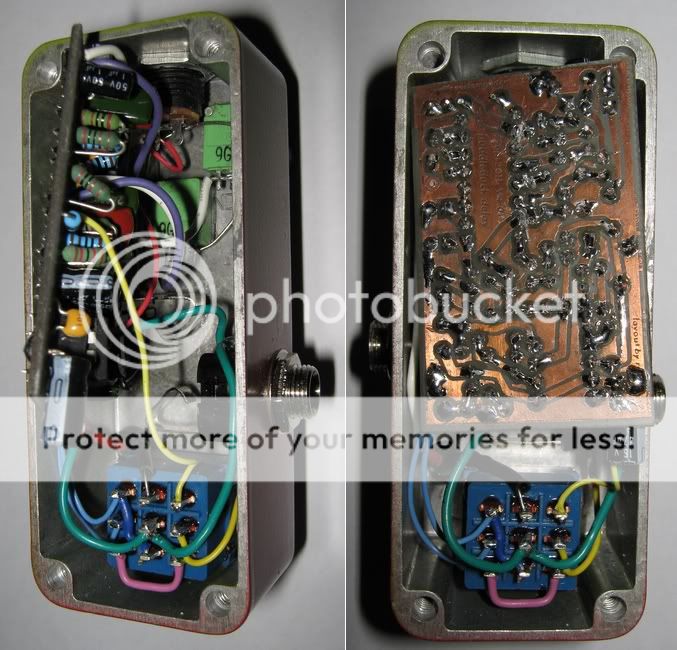
outs:
guts: tighter than a nuns nasty in there
[note, the electro in the bottom right corner, I rotated and drilled a new earth hole for, that way I was able to get a taller (but skinnier) cap in there so I could bend it over to take up less room hightwise]
got a piece of transparency in there (not shown) too so as to insulate the board and any shortable parts from the housing.

Anyone had thinking like me to improve this type of delay with the deluxe memory man or pitch pirate oscillator?
I will do some try outs and make a layout.
-
rocklander
- Old Solderhand
Information
- Posts: 2726
- Joined: 18 Apr 2008, 11:33
- my favorite amplifier: my jansen bassman 50
- Completed builds: rebote 2.5; supreaux; odie; heartthrob tremolo; ross phaser; dr. boogey; thor; baja black toast; slow gear attack, rebote, tri-vibe, small clone, little angel, magnus modulus, echo base, hex fuzz, big muff, 22/7.
- Location: Rotorua, New Zealand
- Has thanked: 1406 times
- Been thanked: 231 times
- Contact:
all?Matros wrote:Hi all.
There is at least one error in all posted diagrams and layouts. Pin 4 of the PT2399 should be connected to the ground. I wonder why nobody did not noticed this, because the connection is clearly visible on the original PCB.
mine is.
https://www.freestompboxes.org/viewtopic ... 80#p162203
world's greatest tautologist ...in the world
Ronsonic wrote:...the lower the stakes the more vicious the combat.
atreidesheir wrote:He should be punched in the vagina.
-
madbean

Information
pin4 is connected to ground internally via a 10R resistor. It works either way.
Sorry, somehow I missed this layout.
madbean, yes, it works. But I think that ground combining through weak internal resistor of a CMOS IC is not a good idea. At least such application is not documented in the PT2399 datasheet.

I do that, yes 4 should be connected to the ground!Matros wrote:Hi all.
There is at least one error in all posted diagrams and layouts. Pin 4 of the PT2399 should be connected to the ground. I wonder why nobody did not noticed this, because the connection is clearly visible on the original PCB.
-
rocklander
- Old Solderhand
Information
- Posts: 2726
- Joined: 18 Apr 2008, 11:33
- my favorite amplifier: my jansen bassman 50
- Completed builds: rebote 2.5; supreaux; odie; heartthrob tremolo; ross phaser; dr. boogey; thor; baja black toast; slow gear attack, rebote, tri-vibe, small clone, little angel, magnus modulus, echo base, hex fuzz, big muff, 22/7.
- Location: Rotorua, New Zealand
- Has thanked: 1406 times
- Been thanked: 231 times
- Contact:
that's understandable.. it's pretty smallMatros wrote: Sorry, somehow I missed this layout.
world's greatest tautologist ...in the world
Ronsonic wrote:...the lower the stakes the more vicious the combat.
atreidesheir wrote:He should be punched in the vagina.
-
mictester

- Old Solderhand
Information
A word of advice to anyone contemplating building one of these - put 100n capacitors from the input and from the output of the 78(L)05 to ground. These capacitors should be as close as possible to the pins of the IC (solder them to the track side of the PCB if you have to...
These regulators are superb but suffer from three problems -
1. They're hissy because they're a very old design (shouldn't be a problem in an audio circuit with good supply rail decoupling, but the extra capacitors will help).
2. They're prone to getting upset by proximity to radio signals (I've had them go wild when a mobile phone goes off nearby - the capacitors will tame that sensitivity).
3. They can suffer from spontaneous instability, especially when there's a step-change in the current drawn (the capacitors help to prevent this, too).
The types of capacitor used doesn't really matter, and the value isn't too critical (anything from 33n - 220n will do), but given the choice, 1950s wax-coated types should be used for maximum mojo...
I usually use small monolithic types (with 0.1" lead pitch) which will connect as close to the regulator as possible.
"Why is it humming?" "Because it doesn't know the words!"
-
HEAD

- Resistor Ronker
Good practice. I do that in every design in which I use regulators but did somehow miss that on my DB build.mictester wrote:A word of advice to anyone contemplating building one of these - put 100n capacitors from the input and from the output of the 78(L)05 to ground. These capacitors should be as close as possible to the pins of the IC (solder them to the track side of the PCB if you have to...
These regulators are superb but suffer from three problems -
1. They're hissy because they're a very old design (shouldn't be a problem in an audio circuit with good supply rail decoupling, but the extra capacitors will help).
2. They're prone to getting upset by proximity to radio signals (I've had them go wild when a mobile phone goes off nearby - the capacitors will tame that sensitivity).
3. They can suffer from spontaneous instability, especially when there's a step-change in the current drawn (the capacitors help to prevent this, too).
The types of capacitor used doesn't really matter, and the value isn't too critical (anything from 33n - 220n will do), but given the choice, 1950s wax-coated types should be used for maximum mojo...
I usually use small monolithic types (with 0.1" lead pitch) which will connect as close to the regulator as possible.
Good note, mictester!
Actually, need of such capacitors and other useful application notes are described in the IC datasheet. Please see the picture. Placing a diode from output to input is also a very good practice, especially when you're feeding a device with low current consumption and have big output capacitor installed.
Actually, need of such capacitors and other useful application notes are described in the IC datasheet. Please see the picture. Placing a diode from output to input is also a very good practice, especially when you're feeding a device with low current consumption and have big output capacitor installed.
-
mictester
- Old Solderhand
Information
As I had a batch of PT2399s delivered the other day, I thought I'd give this circuit a try...
PnP to follow!
- PCB Layout
"Why is it humming?" "Because it doesn't know the words!"
-
fretzburner
- Breadboard Brother
Hi i build this layout and working ok with small corrections.Connection between C11 and C11a and the one jumpered with red.Cut connection from IC2 pin13 to R11and make the red jumper.please check.Thanks for the layout mictester

image host
image host

could the endless repeats be done in the DBD just like in the rebote delays? thanks!
huhhhhh?
-
rocklander
- Old Solderhand
Information
- Posts: 2726
- Joined: 18 Apr 2008, 11:33
- my favorite amplifier: my jansen bassman 50
- Completed builds: rebote 2.5; supreaux; odie; heartthrob tremolo; ross phaser; dr. boogey; thor; baja black toast; slow gear attack, rebote, tri-vibe, small clone, little angel, magnus modulus, echo base, hex fuzz, big muff, 22/7.
- Location: Rotorua, New Zealand
- Has thanked: 1406 times
- Been thanked: 231 times
- Contact:
yupsikheadzraf wrote:could the endless repeats be done in the DBD just like in the rebote delays? thanks!
world's greatest tautologist ...in the world
Ronsonic wrote:...the lower the stakes the more vicious the combat.
atreidesheir wrote:He should be punched in the vagina.
-
Seiche

- Old Solderhand
just started doing the vero version by mictester. I read the DBD might have a slight volume drop when engaged, how could I go about taking care of that? I would replace a resistor with a pot, would changing R6 for a 1k pot do the trick?
-
marshmellow
- Cap Cooler
Clean volume should be ever so slightly above unity gain. Input gain of 2 (360k/180k), output gain of 0,55 (12k/22k). If you want more you could reduce the 22k resistor. That would leave the effect volume unchanged and only boost the clean signal. If you want to boost both, increase the 12k resistor.