Frantone - Peach Fuzz [traced]
- MoreCowbell
- Transistor Tuner
Information
I sent a bunch of pics to AG a while back, but I know he has a lot more important things to worry about these days...
Unfortunately I dont have "wiring" photos (and I can't remember the name of the guy who sent these pics to me....) , but these should get us close. We'll just have to make an educated guess about the pot values and wiring.
I already flipped the trace side photo.
Have fun.
Unfortunately I dont have "wiring" photos (and I can't remember the name of the guy who sent these pics to me....) , but these should get us close. We'll just have to make an educated guess about the pot values and wiring.
I already flipped the trace side photo.
Have fun.
- bajaman
- Old Solderhand
Information
- Posts: 4549
- Joined: 26 Jun 2007, 21:18
- Location: New Brighton, Christchurch, NZ
- Has thanked: 596 times
- Been thanked: 2061 times
I will have a go at it - unless someone else is already doing so - no need for duplication
cheers
bajaman
cheers
bajaman
- MoreCowbell
- Transistor Tuner
Information
I know AG was working on it, but that was a while ago.bajaman wrote:I will have a go at it - unless someone else is already doing so - no need for duplication
cheers
bajaman
I'd do it, but I just don't have time these days.
- bajaman
- Old Solderhand
Information
- Posts: 4549
- Joined: 26 Jun 2007, 21:18
- Location: New Brighton, Christchurch, NZ
- Has thanked: 596 times
- Been thanked: 2061 times
Well - here is what i got so far - feel free to correct or add to it
cheers
bajaman
https://i197.photobucket.com/albums/aa2 ... schem1.jpg
cheers
bajaman
https://i197.photobucket.com/albums/aa2 ... schem1.jpg
- MoreCowbell
- Transistor Tuner
Information
Thought I'd bump this...
- MoreCowbell
- Transistor Tuner
Information
Interesting. Definitely a bit different then the standard opamp fuzzes. Clipping multiple 386's ...bajaman wrote:Well - here is what i got so far - feel free to correct or add to it
cheers
bajaman
https://i197.photobucket.com/albums/aa2 ... schem1.jpg
- bajaman
- Old Solderhand
Information
- Posts: 4549
- Joined: 26 Jun 2007, 21:18
- Location: New Brighton, Christchurch, NZ
- Has thanked: 596 times
- Been thanked: 2061 times
Hi Andrew
Any idea where the collector of the 2N5088 goes? , and how about that pulldown 1 Meg resistor ain the inverting TL022 gain stage - pretty weird stuff - they only used one half of the 022 too
bajaman
Any idea where the collector of the 2N5088 goes? , and how about that pulldown 1 Meg resistor ain the inverting TL022 gain stage - pretty weird stuff - they only used one half of the 022 too
bajaman
- MoreCowbell
- Transistor Tuner
Information
It looks almost like the collector connects to the white wire jumper, and then to the grey wire (V+ ???)bajaman wrote:Hi Andrew
Any idea where the collector of the 2N5088 goes? , and how about that pulldown 1 Meg resistor ain the inverting TL022 gain stage - pretty weird stuff - they only used one half of the 022 too
bajaman
Strange pedal. I used to have one...I wish I still did so I could confirm some of these things.....
- bajaman
- Old Solderhand
Information
- Posts: 4549
- Joined: 26 Jun 2007, 21:18
- Location: New Brighton, Christchurch, NZ
- Has thanked: 596 times
- Been thanked: 2061 times
I am assuming the 1k resistor goes to the led indicator light which is connected to +9v, the same as the schematic for the Frantone Sweet ( yet another big muff) pedal previously posted on DIY Musikding - but what the hell is the 2N5088 for ???, and where does that grey wire ( connected to the white wire??) from the collector go????.
weird
bajaman
weird
bajaman
- pz
- Solder Soldier
The base of the 5088 is connected via 10k||10u to the switch. I'd say that this is a kind of popping eliminator. Attach the collector to some voltage via resistor, just for simulation. When there's a change in the footswitch state, a short impuls to ground is generated by 5088, probably used to mute the signal for a while, to cut out the pop. Engl used something similar in their preamp switching. Just my guess...bajaman wrote:I am assuming the 1k resistor goes to the led indicator light which is connected to +9v, the same as the schematic for the Frantone Sweet ( yet another big muff) pedal previously posted on DIY Musikding - but what the hell is the 2N5088 for ???, and where does that grey wire ( connected to the white wire??) from the collector go????.
weird
bajaman
- bajaman
- Old Solderhand
Information
- Posts: 4549
- Joined: 26 Jun 2007, 21:18
- Location: New Brighton, Christchurch, NZ
- Has thanked: 596 times
- Been thanked: 2061 times
thanks pz, I realize it is only a guess onf yours, but I still cannot see how that would mute the signal.
I must check the Engl schems I have - what value resistor would be appropriate for the collector load and why is it not on the circuit board??
bajaman
I must check the Engl schems I have - what value resistor would be appropriate for the collector load and why is it not on the circuit board??
bajaman
Information
hi guys,
I'm enjoying this site a lot.
I took some photos of my peachfuzz tonight. They are VERY high resolution
I'm too busy right now to reverse engineer it myself. When i get a chance, i'll give it a shot. Tell me if you guys need anything
Keep up the good work!
http://farm3.static.flickr.com/2420/207 ... 6af5_o.jpg
http://farm3.static.flickr.com/2313/207 ... e7f6_o.jpg
http://farm3.static.flickr.com/2269/207 ... 81db_o.jpg
http://farm3.static.flickr.com/2129/207 ... 7a33_o.jpg
http://farm3.static.flickr.com/2089/207 ... bdb5_o.jpg
http://farm3.static.flickr.com/2282/207 ... eb86_o.jpg
- bajaman
- Old Solderhand
Information
- Posts: 4549
- Joined: 26 Jun 2007, 21:18
- Location: New Brighton, Christchurch, NZ
- Has thanked: 596 times
- Been thanked: 2061 times
thanks
bajaman
bajaman
Thanks velcro boy!
there are 3 resistors under the wires that we can't see. Any chances of getting a shot lifting the wires a bit, or even telling us the colours they read?
Same with pot values! I could only read the 10K one.
Thanks again!
snail
there are 3 resistors under the wires that we can't see. Any chances of getting a shot lifting the wires a bit, or even telling us the colours they read?
Same with pot values! I could only read the 10K one.
Thanks again!
snail
- analogguru
- Old Solderhand
Information
Nice photos, nice resolution.... a quarter of the resolution would also giv good results....
Hmmm.... Christmas is coming.... and I would like to see some shots from the directions marked in yellow:
I think with this shots I should be able to finish the schematic and a lot of people could get happy.
analogguru
Hmmm.... Christmas is coming.... and I would like to see some shots from the directions marked in yellow:
I think with this shots I should be able to finish the schematic and a lot of people could get happy.
analogguru
There´s a sucker born every minute - and too many of them end up in the bootweak pedal biz.
Information
yeah, okay. When i get home today, i'll see if i have time to open the pedal up again and mark the values of the components.
@analogguru -- can't you just flip the trace pic over and superimpose the two together?
- analogguru
- Old Solderhand
Information
that would be fine....super velcroboy wrote:yeah, okay. When i get home today, i'll see if i have time to open the pedal up again and mark the values of the components.
Here is a mirrored pic of the track side (from another guts)@analogguru -- can't you just flip the trace pic over and superimpose the two together?
http://analogguru.an.ohost.de/temp/Fran ... rror_c.jpg
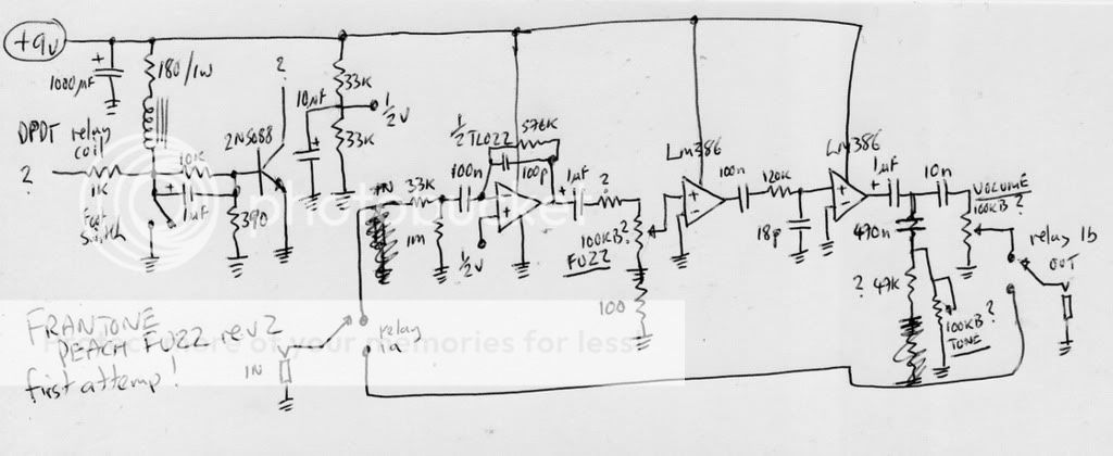
My procedure of tracing is as following:
1.) to make a black/white printout of the mirrored trackside.
2.) mark tracks and eyelets in turquios
3.) draw the components manually in different colors (resistors: pink, semiconductors: orange, capacitors: green)
4.) during 2 and 3 look for ground and V+ and mark those tracks in darkblue and red
5.) After finishing this: trace the schematic from this drawing
As you can see, for the reason of my procedure I dont have experience in superimposing 2 pictures together... sorry
analogguru
There´s a sucker born every minute - and too many of them end up in the bootweak pedal biz.