Hi
few days ago a guy give me a fender fuzz wah pcb. unfortunately he had throw away the pedal box many years ago and just keep the pcb. it s the same pcb you can see here http://members.chello.nl/~t.heertjes/wah/73cbspri.jpg
the pcb back is labeled 1967 c peterson + a serial number.
the fuzz is working. but i don t have the pots for volume and wah and can t find anywhere over the net a schematic for the early fender fuzzwah version.
So if someone have a schem or hi rez guts pics so i can find where and how are the potentiometers wired; i could give this old pcb a new life...
thanks for any infos you have to help me...
audioforge
Fender - Fuzz Wah ( 1st edition ) [schematic]
-
WhiteKeyHole

- Cap Cooler
Can you post some high-resolution photographs clearly showing the trace side and various angles of the component side? Then we can draw up a schematic.
Thank you.
Thank you.
-
analogguru
- Old Solderhand
Information
I thought we had that already, but I couldn´t find the thread.
Anyway, here is the schematic.
analogguru
Anyway, here is the schematic.
analogguru
There´s a sucker born every minute - and too many of them end up in the bootweak pedal biz.
-
borislavgajic
- Opamp Operator
Information
- Posts: 1542
- Joined: 27 Feb 2008, 14:23
- Completed builds: ...script phase90,ETI phaser,Ross phaser,mutronC200,vox wah,WH10,FW-3,mutronIII,DrQuack,Penfoldautowah,Tubezipper,
Dipthonizer,seekwah,Talkingpedal,morleywha
...soulpreacher,dynacomp,compulator
...buzzaround,fuzzfactory,screwdriver,sho,superdouper,St-9,RogerMayer octavia,Tychobrahe octavia,paralelluniverse,string damper,slowgear
...CE-2,ibanez fL301,EH theCloneTheory
EHX bassmicrosynth,EHX EnglishMuffin,Tube Phaser,springtubereverb ,greyDOD,FulldriveII mosfet,OCD,VOX repeat percussion,RingStinger,Meatball,12stage phaser.... - Location: Sombor , Serbia
- Has thanked: 131 times
- Been thanked: 281 times
WhiteKeyHole wrote:Can you post some high-resolution photographs clearly showing the trace side and various angles of the component side? Then we can draw up a schematic.
Thank you.
Scheme is here,but guts are welcommenzy for making cloned PCB so please post some nice sharp photos?
thanks
Boris
-
Bernardduur
- Transistor Tuner
Nice!
What are the transistors?
What are the transistors?
'No more....... loud music.......'
Follow my love for pedals and amps on https://bernardduur.blogspot.com and https://www.instagram.com/bernardduur1
Follow my love for pedals and amps on https://bernardduur.blogspot.com and https://www.instagram.com/bernardduur1

-
borislavgajic
- Opamp Operator
Information
- Posts: 1542
- Joined: 27 Feb 2008, 14:23
- Completed builds: ...script phase90,ETI phaser,Ross phaser,mutronC200,vox wah,WH10,FW-3,mutronIII,DrQuack,Penfoldautowah,Tubezipper,
Dipthonizer,seekwah,Talkingpedal,morleywha
...soulpreacher,dynacomp,compulator
...buzzaround,fuzzfactory,screwdriver,sho,superdouper,St-9,RogerMayer octavia,Tychobrahe octavia,paralelluniverse,string damper,slowgear
...CE-2,ibanez fL301,EH theCloneTheory
EHX bassmicrosynth,EHX EnglishMuffin,Tube Phaser,springtubereverb ,greyDOD,FulldriveII mosfet,OCD,VOX repeat percussion,RingStinger,Meatball,12stage phaser.... - Location: Sombor , Serbia
- Has thanked: 131 times
- Been thanked: 281 times
And as you can see AC/DC guitarist use one too........or it is becouse those legs?
Boris
Boris
Information
- Posts: 2
- Joined: 20 Oct 2010, 19:45
- Location: france
whoo...
Thanks a lot Analogguru for the schematic
i should have a 50k rev log for a fender tremolo amp and a 250k log.. so i could try if it work..
Lolbou. all the transistors on my pcb have propriotary numbers but i ve found that the wah part have 3 germanium PNP 2N404A. the others ones are for the fuzz. there s 2 germanium diodes in the fuzz signal.
the fuzz part can be easily cloned (if you can source the germanium diodes) but the wah need a tapped inductor ! so forget it IMHO.
there s good guts pics on ebay https://cgi.ebay.com/Vintage-1970s-Fend ... 2eb05e20ea
scroll down the page and grab the pics while you can...
thanks guys .you re great
audioforge
Hi All,
I have one of these pedals and it's been pretty worked over by a previous person. They left a few wires hanging and it doesn't have a battery connector. I'm a little lost at this point.
I see people mentioning that there is a schematic available but I don't see it, nor can I find it on google or in any of the archives here. Can anyone help?
Thanks so much in advance!
-
jrod
- Resistor Ronker
Attached!pedalfreak9847 wrote:Hi All,
I have one of these pedals and it's been pretty worked over by a previous person. They left a few wires hanging and it doesn't have a battery connector. I'm a little lost at this point.
I see people mentioning that there is a schematic available but I don't see it, nor can I find it on google or in any of the archives here. Can anyone help?
Thanks so much in advance!
 FENDER FUZZ WAH SCHEMATIC.pdf
- (277.06 KiB) Downloaded 1081 times
Wow, thanks jrod!
It's amazing that I got as much right as I did without the schematic. As an electrical engineer working the field of audio CODECs, this is one messed up design!
Not that it doesn't work, but using the positive voltage of the battery for the chassis ground is pretty unconventional. Without the schematic, it took me a bit to convince myself that the positive terminal was really ground (and in fact switched through the two pole jack). This was due to the missing wires.
I got the have the fuzz working without the schematic, but the wah was a bit more complicated, not to mention that I had to disassemble the tapped inductor to re-solder a connection, always risky business.
I know I'm going to get this thing fully working and it'll not even sound that good.
oh well, part of the adventure...
Nice community you have here! Thanks again.
The positive ground is due to the PNP transistors, no different than a PNP Fuzz Face. When you re-assemble the inductor, note that the top part of the core twists to adjust the inductance value. You will probably have to adjust it by ear once the pedal is working.
Well it only works because this is a stand-alone entity running from a battery. You certainly wouldn't want to chassis "ground" a 9V wall adapter's positive terminal unless you're very sure that there is no earth ground reference cause once you plug into your third prong powered amp through the pedal, currents gonna flow. Likely not dangerous, but bad things might happen.Mr. Bill wrote:The positive ground is due to the PNP transistors, no different than a PNP Fuzz Face. When you re-assemble the inductor, note that the top part of the core twists to adjust the inductance value. You will probably have to adjust it by ear once the pedal is working.
There's no reason why the ground side couldn't have been switched rather than the 9V side....I've just seen the ground side switch as a lot more common. In fact, the second gen Fender Fuzz Wah with the two opamps used ground side switching. I figure this was the result of some ECL logic design that would have been popular at the time.
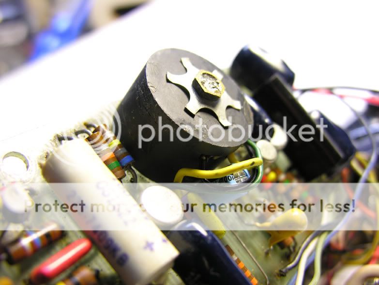
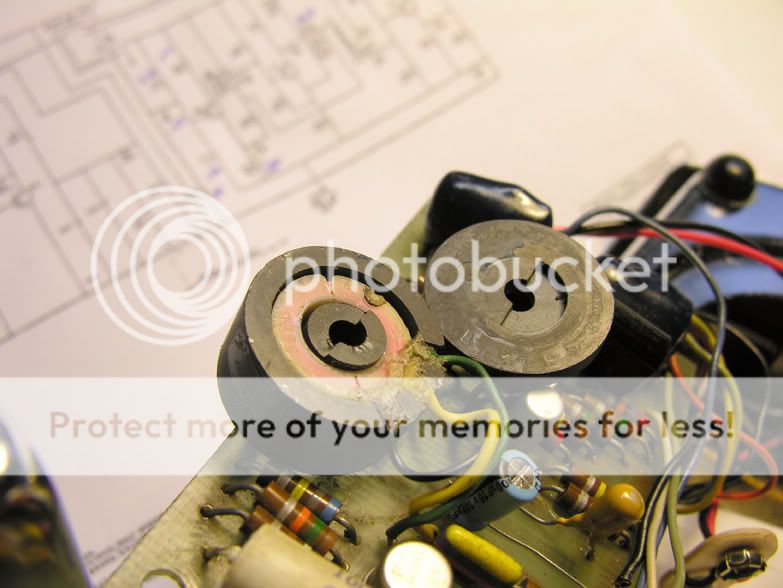
Concerning the inductor, how does adjusting the coil radially affect the inductance? I saw two (what I presume) were two ferrous cores in the middle, but they looked fairly monolithic to me. Are they different? The insulation on the wires coming out of the inductor core are pretty stiff (from age) and I really don't want to bend them that much, so knowing what I'm doing before I adjust it would be helpful. A blow dryer should help with bending the wires too.
Sorry that it took a while to shoot these photos. I don't know what your pedal has, but this is what mine has. The choke is wound on a plastic bobbin and encased in a ferrite core. The top of the core removes and if you look at the center section, it has a half moon shaped adjustment area. As you rotate the top disc, the inductance of the coils changes. The entire unit bolts down to the board with a brass screw and nut.

Information
if anyones still interested i've got one of these in the mail i'll take apart 
the toyroom effects guy.
"My Pedals Kicked Ass! Don't be Jealous Boutique Builders! My Pedals Had Tone! AND YOU KNOW IT! Go Buy the Same LOUSY shit!"- Ken.
"My Pedals Kicked Ass! Don't be Jealous Boutique Builders! My Pedals Had Tone! AND YOU KNOW IT! Go Buy the Same LOUSY shit!"- Ken.
-
sinner
- Old Solderhand
Information
- Posts: 4709
- Joined: 06 Nov 2008, 17:16
- Location: ...no more
- Has thanked: 1031 times
- Been thanked: 909 times
Please do
-
borislavgajic
- Opamp Operator
Information
- Posts: 1542
- Joined: 27 Feb 2008, 14:23
- Completed builds: ...script phase90,ETI phaser,Ross phaser,mutronC200,vox wah,WH10,FW-3,mutronIII,DrQuack,Penfoldautowah,Tubezipper,
Dipthonizer,seekwah,Talkingpedal,morleywha
...soulpreacher,dynacomp,compulator
...buzzaround,fuzzfactory,screwdriver,sho,superdouper,St-9,RogerMayer octavia,Tychobrahe octavia,paralelluniverse,string damper,slowgear
...CE-2,ibanez fL301,EH theCloneTheory
EHX bassmicrosynth,EHX EnglishMuffin,Tube Phaser,springtubereverb ,greyDOD,FulldriveII mosfet,OCD,VOX repeat percussion,RingStinger,Meatball,12stage phaser.... - Location: Sombor , Serbia
- Has thanked: 131 times
- Been thanked: 281 times
sinner wrote:Please do
-
CHEEZOR
- Diode Debunker
If anybody is interested, I just found the schematic on ebay (https://www.ebay.com/itm/VINTAGE-1976-F ... 27c340922b) and I am willing to bid on it and scan it to upload here if there is interest. Although, Im probably not willing to go as high as crazy collectors. Note: Im totally uninterested in the actual paper copy so if someone else would love to have it then they can bid on it or I could mail it after scanning it. Just let me know cuz it would be better if we weren't bidding against each other.
That is the schematic for the later version with the cast metal case. You can see that there is a dual opamp in the schematic. If anyone is really interested in it I already have a copy of it and can scan it.