Greetings,
As I told you, I wasn't sure how to post it. Know I got it. Tomorrow I will post it here as an attachment. I'm at work and the file is at home. Here we are forbidden to access some sites.
Sorry about the inconvenience.
Cheers
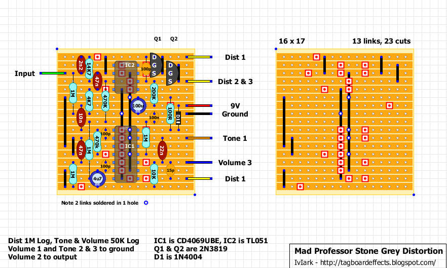
Mad Professor - Stone Grey Distortion [traced]
-
phibes

- Transistor Tuner
Information
It's cool, I used to do the same. The nice thing is you don't have to worry about files going away due to web storage going down. I hate that shit with photobucket.
GuitarlCarl - "TGP = The Gear Polishers"
 Ken
Ken
KenGreetings,
Sorry about the time it took to post. Here it goes the layout as an attachment. If you have any question about it just let me know and I'll be gald to help you.
Cheers
Sorry about the time it took to post. Here it goes the layout as an attachment. If you have any question about it just let me know and I'll be gald to help you.
Cheers
- Attachments
-
 Stone Grey Distortion.pdf
- (207.77 KiB) Downloaded 1053 times
-
BJF

- Resistor Ronker
Hi,
Recall that when an invereter 40XX series is used as an analog amplifier the open loop gain is low and dependent on powersupply and so at 5V gain is at its highest but open loop bandwidtn is at its lowest at a couple of Hertz; at about 8V open loop bandwith is about 7KHz while now the closed loop gain becomes a complicated computation because the open loop bandwidth is low.
What does this mean in layman terms?
It means that the exact voltage at which the circuit is powered will affect the sound and especially how distortion is formed
At your service
BJ
BJF Electronics
Sweden
-
dv8r601

- Breadboard Brother
2n3819gearstack wrote:I dont have 2n3819....I only got j201 and 2n5457. I heard it cant be a straight substitute without altering the leg of the fet. Can someone help me with a simple schem or layout on the clipping part...thanks
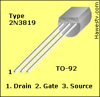
2n5457

Take the center leg if looking at front, swap it around so the source is now on the outside, and the gate is in the middle, take a piece of stripped wire jacket and cover the bent lead so it doesn't short out. Easy as that. just make sure the pinouts match the layout that your going to use, otherwise it (potentially)won't sound right.
OR
In a much more complicated fashion:
You could move the link up one spot on each jfet and spin Q2 around so that the same legs are tied together and that the signal effectively goes thru like its supposed to,(Q1-D+S->G INTO Q2 G->D+S), BUT that would involve trace cuts and components to move around, etc.. I'm lazy as hell, so the simplest way works for me with things like this. YMMV
Just built one of these and it sounds very good !! Very open sounding and not congested at all like other circuits........Gain is a bit too short for me though (palm mutes don't really "chug")..... What should I change i order to achieve more gain ?
-
Ichabod_Crane

- Resistor Ronker
I never built it, and I don't know too much the CD4069UBE chip, but I think you could try to replace the 4.7k with 1k or lower, this will give you more gain, but it will push treble, too. You should have to replace the 47nF close to the 4.7k with a 100nF, 220nF or more to move the frequency back to the low end.
I don't know how much clip the jfet, maybe silicon diodes (1N4148) can clip more and get more distortion, but in this case the sound could change.
I don't know how much clip the jfet, maybe silicon diodes (1N4148) can clip more and get more distortion, but in this case the sound could change.


-
EmmG
- Breadboard Brother
I also like the tone, but thought it needed more distortion, especially as it was marketed as being good for drop tunings. I've built two from different layouts.
I experimented changing the 4.7k/47n to 1k/220n, as said above, which was good enough. I also tried 470ohm/470n for a very extreme metal distortion that was too noisy for me but sounded good.
I experimented changing the 4.7k/47n to 1k/220n, as said above, which was good enough. I also tried 470ohm/470n for a very extreme metal distortion that was too noisy for me but sounded good.