EMG - AB Afterburner
-
CHEEZOR

- Diode Debunker
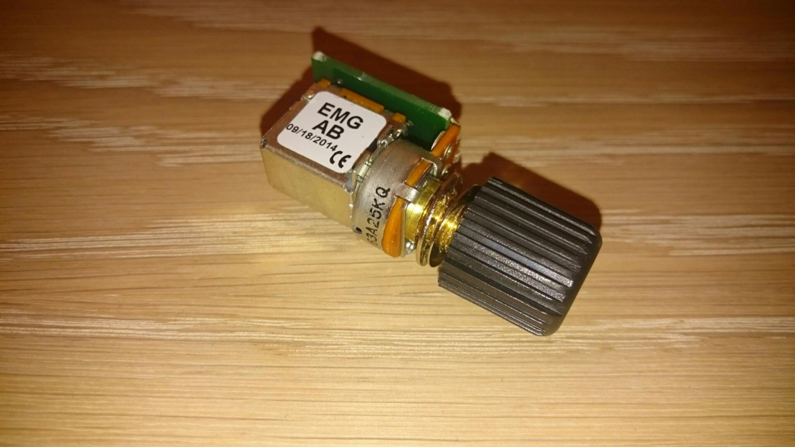
I just got one of these because it was pretty cheap and I knew there were folks (at least one) here that are interested in the circuit. I don't have time to trace it out, but I have some pics that may make the process pretty simple. If there are any questions about values then just ask me and I'll get back to you as soon as possible. 
- Attachments
-
-
-
alexradium
- Resistor Ronker
if you can add the component values,thanks a lot,i'd like to make a comparison with other boosters i have.CHEEZOR wrote:I just got one of these because it was pretty cheap and I knew there were folks (at least one) here that are interested in the circuit. I don't have time to trace it out, but I have some pics that may make the process pretty simple. If there are any questions about values then just ask me and I'll get back to you as soon as possible.
-
CHEEZOR
- Diode Debunker
I started looking at this circuit a while ago, but I never got around to drawing a schematic. Here is a better quality image: https://img526.imageshack.us/img526/320 ... ropped.jpg
a) All the blue circles mean ground.
b) All the red lines are the traces that cannot be seen in the picture. They might not be correct, but they are as close as I could figure out using my multimeter at the time. Also, there are probably more that I did not find on the other side of the board.
c) The 2 big blobs of solder are the lugs of the push pull switch to turn the effect on or off.
d) I dont know what the values of the unmarked caps are. Im assuming that if we drew out a schematic then the values would become pretty obvious to some here who have experience with boost circuits.
e) The big red "?" is there because those points were connected according to the multimeter, but I did not see how. There are traces on the back side that I could not see though.
I have a parts list somewhere, but I will have to find it. Im pretty sure I wrote down all the values that were written, but you can probably see most of them in that pic.
-
CHEEZOR
- Diode Debunker
I found the list I made.
Parts that are labeled:
Resistors:
1002 = 10K
1004 = 1M
2001 = 2K
4992 = 49.9K
4993 = 499K
Caps:
2.2uF
1.0uF
Op amp text (as best as I can read):
Line 1: OP191G
Line 2: #0809
Line 3: M3930
I think the part name is the first line since that is the google search which brings up the most Op Amp related results. The other parts are unmarked. The pot is probably marked and Im assuming that is 25K like all the other EMG pots, but I would have to double check to be sure and I dont know where I put the damn thing at the moment.
I just ran across this: viewtopic.php?f=3&t=15541 which is probably very similar. Doesn't look exact (just from the number of caps), but probably still close.
-
alexradium
- Resistor Ronker
thank you,very kind,you did a great job.CHEEZOR wrote:I found the list I made.
Parts that are labeled:
Resistors:
1002 = 10K
1004 = 1M
2001 = 2K
4992 = 49.9K
4993 = 499K
Caps:
2.2uF
1.0uF
Op amp text (as best as I can read):
Line 1: OP191G
Line 2: #0809
Line 3: M3930
I think the part name is the first line since that is the google search which brings up the most Op Amp related results. The other parts are unmarked. The pot is probably marked and Im assuming that is 25K like all the other EMG pots, but I would have to double check to be sure and I dont know where I put the damn thing at the moment.
I just ran across this: viewtopic.php?f=3&t=15541 which is probably very similar. Doesn't look exact (just from the number of caps), but probably still close.
yes it looks very similar to PA2,this one is made with a single opamp,PA2 is double,one with buffer and one boost with pot,and the switch deviates the signal from the 2 sides.
AB does the buffer with switch,bypassing the pot,i guess its a 500k.
also,one side of the pot should go to pin 2 not 3,first cap in input should be 100nF.
i don't think its really necessary to draw a new schem or layout for this,it should be enough to change some values to the PA2 in that thread,anyway,PA2 is more guitar oriented,AB is good also for a bass,that's what i see in the circuits.
-
alexradium
- Resistor Ronker
yes,it makes perfect sense.CHEEZOR wrote:I just wanted to confirm that my Afterburner pot says 25k.
the resistor on the left should be 2k also.
-
alexradium
- Resistor Ronker
AB has a lower pot resistance ,that is one reason for being less noisy if possible.askwho69 wrote:Nice one guys, i was looking for this one.. PA2 has white noise on it... they said AB is better that pa2... does anyone agree with that? i schematic is better for comparison
schematic is not difficult to draw,you have the pics and most of the component values,those missing are easily predictable.
-
alexradium
- Resistor Ronker
cap in input to ground could be anything up to 100pFaskwho69 wrote:I want to draw the schematics but can you please clarify this one?
I wrote some question if you zoom the picture
The question mark - the 1M connection to +9 and negative for 4.5 biasing
input cap to pin 3 usually is 100nF,for less low end decrease to 22n or 10n.
cap from +9V to ground should be 0,15uF
gain pot is connected between pins 2 and 6
-
alexradium
- Resistor Ronker
in order to read a schematic,you need to be able to understand an opamp amplifier,in this case a non inverting one,with a +20 dB gain,nothing more than your average text book/datasheet application.irek81 wrote:Anybody has a proper schematic for afterburner? I do not know how to connect OP191. Anyone did that and it works?
Any single opamp will do,if you use a battery a TL061 is ok.
I'm amazed no one has made a kit for this yet...
I have been wanting to make one fo these for aaaages.
I am glad this thread has sprung up, nice one guy XD
Quick question, does anyone have a PCB layout diagram... There are a few on here, but they aren't very clear.
Ideally, something I can just take and use right off.
EG
http://www.generalguitargadgets.com/pdf/ggg_mbb_pcb.pdf
Something like that would be great XD
-
alexradium
- Resistor Ronker
i did some homework since this is a basic circuit and could be useful to me also.joebot101 wrote:I'm amazed no one has made a kit for this yet...
I have been wanting to make one fo these for aaaages.
I am glad this thread has sprung up, nice one guy XD
Quick question, does anyone have a PCB layout diagram... There are a few on here, but they aren't very clear.
Ideally, something I can just take and use right off.
EG
http://www.generalguitargadgets.com/pdf/ggg_mbb_pcb.pdf
Something like that would be great XD
this is 32x23 mm

if its clear and ok for your use,i can upload the printable layout,otherwise i can mod it to taste.
-
phatt
- Transistor Tuner
Hi alexradium,
I can't see how that pcb could work as pin 1 & 5 are not connected to anything?
Also those 1meg voltage dividers for the offset bias are not ideal.
If running from a 9 volt battery then a 10k/10k divider gives half voltage and then 1 meg to +input.
In the case of input on the inverting input you don't need the bias just a cap as the positive input is already DC referenced.
As a rule the positive input of most opamps need a DC path to ground.
Better minds here might explain it better.
If you wish I can draw up a schematic for you to work from.
Phil.
-
alexradium
- Resistor Ronker
the only errors are that V+ goes to pin7 and signal out is on pin 6,but that is not important now,its already fixed in my layout,i was just asking if its ok in dimensions,type and layout of components,then i can give the layout.phatt wrote:Hi alexradium,
I can't see how that pcb could work as pin 1 & 5 are not connected to anything?
Also those 1meg voltage dividers for the offset bias are not ideal.
If running from a 9 volt battery then a 10k/10k divider gives half voltage and then 1 meg to +input.
In the case of input on the inverting input you don't need the bias just a cap as the positive input is already DC referenced.
As a rule the positive input of most opamps need a DC path to ground.
Better minds here might explain it better.
If you wish I can draw up a schematic for you to work from.
Phil.
Regarding the schematic,it is correct 1:1 with EMG unit,so any complaint about different design could be redirected to the company.
Information
- Posts: 2
- Joined: 22 Jan 2017, 15:20
Any schematic for the AB (After Burner) EMG.And yes it´s a 25K pot.