Updated schematic
Rockett - Animal Overdrive [traced]
-
Manfred

- Tube Twister
Information
- Posts: 1945
- Joined: 04 Apr 2009, 23:42
- Has thanked: 1675 times
- Been thanked: 1360 times
-
alexradium
- Resistor Ronker
Is this recent?
Very similar to the Blue Note,just the pot gain and some resistors different,best way to save product cost and design....i guess this was a Wampler's project,maybe slightly refined later.
what about that Indyguitarist?
Very similar to the Blue Note,just the pot gain and some resistors different,best way to save product cost and design....i guess this was a Wampler's project,maybe slightly refined later.
what about that Indyguitarist?
-
Manfred
- Tube Twister
Information
- Posts: 1945
- Joined: 04 Apr 2009, 23:42
- Has thanked: 1675 times
- Been thanked: 1360 times
Here the corrected schematic.
The DC-input protection diode polarity was wrong.
The OP-amp output was wrong labeled.
The DC-input protection diode polarity was wrong.
The OP-amp output was wrong labeled.
-
nooneknows

- Resistor Ronker
Disappointing, nothing more than a sort of timmy without the output OAmp.
-
IvIark
- Tube Twister
Information
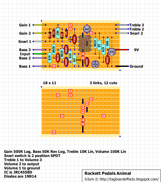
2 is also the inverting input and 3 non-inverting. Verified vero layout, thanks for the scheme
"If anyone is a 'genius' for putting jacks in such a pedal in the only spot where they could physically fit, then I assume I too am a genius for correctly inserting my legs into my pants this morning." - candletears7 - TGP
-
Manfred
- Tube Twister
Information
- Posts: 1945
- Joined: 04 Apr 2009, 23:42
- Has thanked: 1675 times
- Been thanked: 1360 times
Thanks for the hint and the strip board layout.IvIark wrote:2 is also the inverting input and 3 non-inverting. Verified vero layout, thanks for the scheme
Corrected schematic:
Updated schematic
Hi, Manfred. Thank you for your nice schematics.
I have a question. +VS is connected to the 7th pin of JRC4558 in your schematics.
In IvIark's layout, I think +VS is connected to the 8th pin.
Which is right?
I have a question. +VS is connected to the 7th pin of JRC4558 in your schematics.
In IvIark's layout, I think +VS is connected to the 8th pin.
Which is right?
-
alexradium
- Resistor Ronker
being a 4558 chip,its gotta be pin 8.Sept29 wrote:Hi, Manfred. Thank you for your nice schematics.
I have a question. +VS is connected to the 7th pin of JRC4558 in your schematics.
In IvIark's layout, I think +VS is connected to the 8th pin.
Which is right?
-
Manfred
- Tube Twister
Information
- Posts: 1945
- Joined: 04 Apr 2009, 23:42
- Has thanked: 1675 times
- Been thanked: 1360 times
Sorry for the issues with the OP-amp pin designations.
Thanks for the hints.
Here the corrected schematic:
Updated schematic
Thanks for the hints.
Here the corrected schematic:
Updated schematic
-
indyguitarist
- Resistor Ronker
Kinda but not quite.alexradium wrote:Is this recent?
Very similar to the Blue Note,just the pot gain and some resistors different,best way to save product cost and design....i guess this was a Wampler's project,maybe slightly refined later.
what about that Indyguitarist?
We 'worked' together for a few months about 5 years ago. I came up with the schematic for the afterburner (which became the flexdrive) and had built a proto for a light overdrive that was a super simple build which I guess eventually became the blue note. We (me or Wampler Pedals) no longer have any affiliation, whatsoever, with Rockett now.
Any chance to see the PCB layout guys?
Thanks in advance
Thanks in advance
-
Manfred
- Tube Twister
Information
- Posts: 1945
- Joined: 04 Apr 2009, 23:42
- Has thanked: 1675 times
- Been thanked: 1360 times
sorry, I sold the Animal after tracing.
-
roberttomasz
- Breadboard Brother
Schematic +VR = 470k-470k ,,, oryginal effect- +VR = 47k-47k ?????
-
Manfred
- Tube Twister
Information
- Posts: 1945
- Joined: 04 Apr 2009, 23:42
- Has thanked: 1675 times
- Been thanked: 1360 times
Thanks for the hint, you are right!roberttomasz wrote:Schematic +VR = 470k-470k ,,, oryginal effect- +VR = 47k-47k ?????
Updated schematic
-
roberttomasz
- Breadboard Brother
4558 - IN +(3) ,, IN-(2),,OUT (1),, +9V/(8). Dioda 4001 ma być odwrotnie !!!!!
-
Manfred
- Tube Twister
Information
- Posts: 1945
- Joined: 04 Apr 2009, 23:42
- Has thanked: 1675 times
- Been thanked: 1360 times
Thank you very much for the hint.roberttomasz wrote:4558 - IN +(3) ,, IN-(2),,OUT (1),, +9V/(8). Dioda 4001 ma być odwrotnie !!!!!
Thanks for the work on this, I built on vero and really love this pedal. I want to make one with a second stomp instead of a switch for the snarl, I'd also like to be able to increase the volume on the snarl, either a fixed boost or better yet a variable boost set by an internal trim pot. I'm new to this so if anyone could assist with some direction I'd be grateful.
-
Manfred
- Tube Twister
Information
- Posts: 1945
- Joined: 04 Apr 2009, 23:42
- Has thanked: 1675 times
- Been thanked: 1360 times
Should the boost mod works in both snarl settings?either a fixed boost or better yet a variable boost set by an internal trim pot.
Believe the snarl is either engaged for the modded Plexi sound or not for the non-snarl/modded sound, so just want it when snarl is engaged. My best idea so far is to add a simple boost circuit to the snarl side (micro amp, EP boost). Gonna give it a go today.
-
HamishR
- Breadboard Brother
From a technical POV this may be "disappointing" but from a player's POV it's just fine.  The Animal, Blue Note and now the Majestic are all very similar but they sound great! For such simple circuits they work exceptionally well. I actually think it's extremely clever to get such cool sounds from so few parts. I'm no electronics guy, just someone who loves guitar and getting great sounds. So for me these circuits are amazing. All three pedals sound good and different enough from each other to justify having each one.