http://www.muzique.com/schem/filter.htmmiklax wrote:By the way..
What do you think about the active filter section?
Any Idea on how to calculate the corner frequency for each of the switch positions?
https://www.dropbox.com/s/l1p41wjfl27o8zq/Untitled.jpg
Cheers!
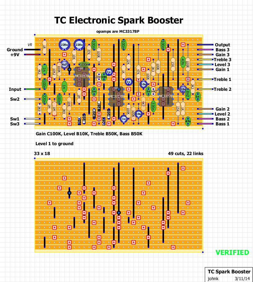
TC Electronic - Spark Booster [traced]
-
alexradium

- Resistor Ronker

-
johnk
- Resistor Ronker
BTW, I drew up a veroboard layout for it, but it's huge at 33x18 so it won't fit in a 1590B. I would probably fit in a 125 but i'm just going to use a 1590B.
if anyone is interested, i'll post the layout after I build and verify it.
if anyone is interested, i'll post the layout after I build and verify it.
-
johnk
- Resistor Ronker
my vero is pretty huge at 33 x 18, but at least it's verified. 
I preferred mine to have a more open top end so I removed C2 (1n cap from miklax's schematic), but it still shown on my vero (second 1n cap from the left).
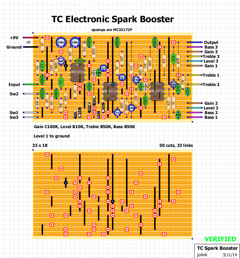
I preferred mine to have a more open top end so I removed C2 (1n cap from miklax's schematic), but it still shown on my vero (second 1n cap from the left).
Great Work!!
I'm glad to finally contribute to this community, that helped me so many times!
When I built mine.. and despite the fact it already has 1M resistor on the Input, and 100K on the output.. It still makes a very loud Pop noise using a regular truebypass wiring..
Any ideas?
Cheers!
I'm glad to finally contribute to this community, that helped me so many times!
When I built mine.. and despite the fact it already has 1M resistor on the Input, and 100K on the output.. It still makes a very loud Pop noise using a regular truebypass wiring..
Any ideas?
Cheers!
-
johnk
- Resistor Ronker
that's strange. mine makes no pop at all when using a true bypass.
thanks for posting the schemo!
if yours is popping, i'd first make sure that the VR+ connections are going to the right places, otherwise it it'll put DC on the output and cause huge popping.
thanks for posting the schemo!
if yours is popping, i'd first make sure that the VR+ connections are going to the right places, otherwise it it'll put DC on the output and cause huge popping.
-
johnk
- Resistor Ronker
sorry it took so long but I finally got around to trying the 33178's and it sounds the same as the 33172's so i'll just leave them in there since that's what the original has in it.fixxe wrote:What's the verdict?johnk wrote:I finally just got them so i'll try the 33178's in it soon.
-
copachino
- Solder Soldier
thanks, would be amazing to have a pcb layout, or maybe and OSH park shared projecto fot this little big monster