
Vertex has (had?) 2 Axis Wahs, the normal one and the "NOS" one.
One of the users offered to loan his NOS to someone if they were willing to de-goop it and find out what it really was,
As luck would have it, that user lived near me so I offered my services to de-goop and trace it.
And in another stroke of luck, he also had a BBE Ben Wah so I could do a comparison between the Vertex NOS Axis Wah and its "Supposed" cousin the BBE Ben Wah.
It took me a little longer than it should have since my heat gun died about a week or so before the Vertex meltdown.
But still, I didn't break any parts during the de-gooping process.
Although one of the transistors did break shortly after
So lets get one with it and show you some pictures...
See that little "NOS" on the box on the right?
That's the ONLY thing that indicates that that is the NOS version. Wonderful.
So what does this NOS gem look like on the inside?
(I had already started peeling the goop off when I took this pic).
That PCB looks a little funny doesn't it?
We are only just getting started here.
No need to show a bunch of de-gooping progress pics so here it is free of goop:
(Yeah I know, looks like I brutalized it a bit. My heat gun died about a week before I tackled this project)
Don't you just love that customized PCB trimming?
Now how about this little pic of the PCB from the BBE Ben Wah with the Vertex modified PCB overlaid on top:
Anyone notice anything missing?
Being that this PCB is from the Vertex NOS Axis Wah.
How about some NOS parts?
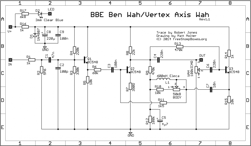
Heres the schem.
And much thanks to Matt for cleaning up my original schematic.
Although lug 1 on the "Body" or "Q" pot is not connected to anything in either the BBE or the Vertex
(Now how many minutes before Ivlark does a vero layout of this?
A few notes:
C1, C2: Greenies
C3, C4, C7, C9: Box
C5: Ceramic Disc
Wah Pots:
BBE: HOSS PT25 SB104
Vertex: 295S1314
Smallbear Elec: SKU 2601B (The Black Bear, 100K)
http://www.smallbearelec.com/servlet/Detail?no=582
The ONLY difference between the BBE and the Vertex NOS versions:
1. The Wah Pots
2. The BBE model I had, has carbon film resistors. I contacted Paul Gagon (The VP of Technology at BBE) and he told me that BBE went to metal film resistors near the end of 2009. Serial number on the BBE is : 200909087 which by my guess means it was made in September of 2009.
Paul confirmed this and added that it was the 87th Wah made in September 2009.
He was also very nice and thanked me for my "detective" work on this.
He seemed like the kind of guy I would enjoy having a beer with at the local pub/bar.
And here we have an overlay showing the taper of each pot:
The pot in the Vertex one topped out at 87.9K, the BBE at 100.2K
( The values for Column 21 are fake, done so that the sizes of each graphic matched up properly)
And the Open Office and MS Excel formatted versions of the pot tapers.


