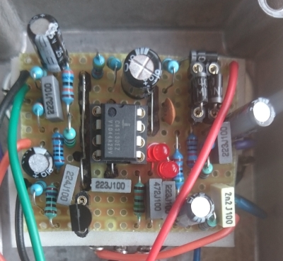
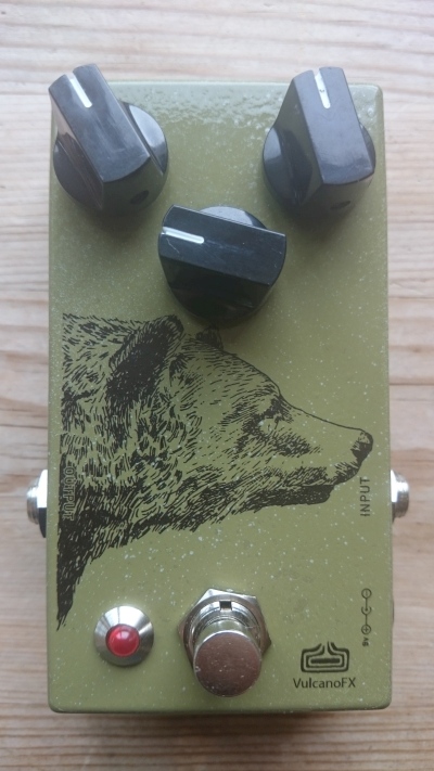
I am the owner of this pedal. The switch became faulty recently, so I decided to replace it and trace the schematic while it was open. Here are some pics of the pedal:


This schematic is different than the Mad Professor incarnation in a few very important ways:
- 1. The MP has a JFET amplifier in the beginning, the BJFE does not
2. The MP gain pot is 1M, the BJFE is 370k
3. The MP tone control effects the AC gain of the output JFET. The BJFE tone control effects the output treble response
Some people have reported their blueberry uses a LM301 IC. I have breadboarded this circuit and can attest that the CA3130EZ sounds much better. The sound is more clear and articulate.
The gain pot is an unusual value of 370K. I made certain this value is correct. When I breadboarded the circuit, I tried a 250K and a 500K. I noticed the 250K sounded identical to the BJFE, whereas the 500K increased in gain too quickly, and became muddy. This may partially explain why the MP version sounds so different. If you truly want to emulate the 370K pot (I couldn't find this actual value pot anywhere), you can use a 2M pot (smallbear) in parallel with a 470K resistor. The upper range of the gain pot does not give much of a difference in sound, and the 250K is just fine IMO.
Although the output volume pot is linear, it helps fine tune the level when adjusting the gain. An audio pot is usually a standard, but a linear has proven useful for me when I use basses with different output.
I believe that R11 and C8 are easter eggs...meaning, they produce no effect and exist only to make tracing this circuit more difficult. Removing them seems to have no effect on the sound. R9 and C7 definitely have an effect...reducing gain and high end. This may be 50% of why this circuit sounds so unique.
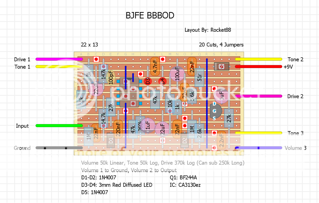
I have made a layout based off of madbean's Yellow Shark, since they are similar in design. I left R11 and C8 for the purists. I did not include the zener diode for the LED (use a bigger resistor). I tied lugs 2 and 3 of the gain pot together if you choose to use a wire on lug 3.
PCB
Size is 48 x 40mm (1.9" x 1.6") and can fit in a 1590B enclosure. The pads are all 1.0mm. The electrolytics are assumed to be 6.0mm with a lead spacing of 2.5mm, although these values can have some tolerance.

Layout
This is the component layout of the above pcb. Notice two of the resistors are stretched a bit. All other resistors are 7.5mm (standard 1/4w), film caps are 5.0mm.

I hope you find this useful.