looks neat. i've never tried this one before. what is that chip? i'm guessing it would not be easy to procure. when did this come out? early 80's?
"You've converted me to Cubic thinking. Where do I sign up for the newsletter? I need to learn more about how I can break free from ONEism Death Math." - Soulsonic
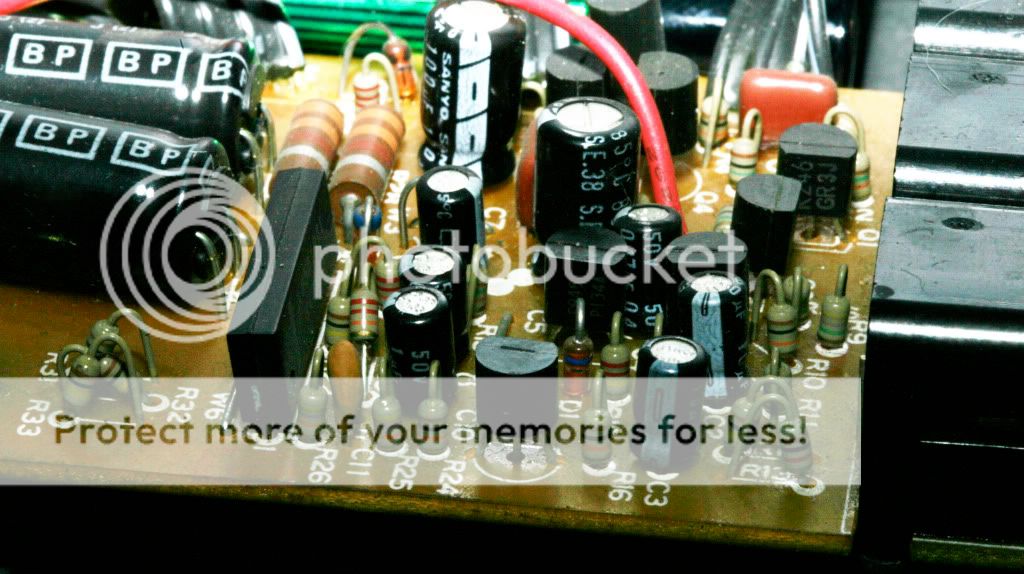
The M5218(AL) is a pretty common SIL dual Opamp often found in Boss pedals as well as other orient developed stuff. Fisrt time I ran into em was whle reversing the CS3 but I've found em in Pioneer CD players as well. They're not rare, easily obtainable and share the same pinning as any standard dual opamp. It's just that we don't see em that much and therefore it scares us. Don't. In some cases the advantage of this SIL baby can be a large help.
yeah, i've seen the SILs in stuff like old tape recorders and the like. and yes, i do find them scary. workin on that, though. i do wonder how this old piece stacks up against simpler DI designs. most are much more spartan.
"You've converted me to Cubic thinking. Where do I sign up for the newsletter? I need to learn more about how I can break free from ONEism Death Math." - Soulsonic
dai h. wrote:re:5218, my understanding was that it's just a 4558 equivalent and nothing special
edit:
to be a bit more clear, this is not to say that it sucks or is a bad choice for all applications. More to say that you probably don't need to find the same exact chip (which may cost you much more nowadays) and a ready available (inexpensive) 4558 will (probably) do.
Reviving this old thread to ask a question. I have this DI and I quite like it. Since I now had a look at the schematic I started to wonder whether it would be possible to get some extra gain out of it? The way it works not it attenuates the signal by roughly 2 dB. If I use it balanced I get an extra 6 dB of gain, so the nett gain is about 4 dB.
Could the op-amp circuit be modified to squeeze some more gain out of this box? Something like 20 dB would be perfect. In my admittedly naive thinking it may be as simple as replacing a couple of resistors. My understanding of electronics is far too little to figure this out by myself. Can anybody help me out? Even if it is only to tell me that my idea is not possible.
Thanks for reviving, I'm interested in this circuit as well.
Alas, I'm no good with balanced signals.
It seems easy to adjust the gain on one channel (change the 1/1 ratio of the R25/R26 resistor pair on IC1a)
However the other channel has IC1b wired as a pure buffer I think.
Btw I'm very intrigued by the auto power part. I need to breadboard that one !
You are raising the same kind of questions that I had. It puzzled me too how the second channel is wired. Wouldn't it make more sense if it was symmetrical? How about if I wire the second channel the same way as the first, with the resistor and capacitor in the feedback loop. Then I can experiment with the R26 resistor value to see what happens.
I looked at the auto power part too but frankly it's not that useful to me. I plan to always use it with phantom power.
That is another thing I would like to modify and that is probably pretty straightforward. I would like to have the phantom power on a separate socket. I think that is easy to do by taking R28 and R29 from the balanced out and rewiring them to an extra connector. Then I can remove the bipolars C12 and C13. Or should I replace them with different value capacitors? I can understand that they are there to block the phantom power but maybe they serve some other purpose as well?
Lol, you have the same kind of answers to the questions that I raised.
I see no apparent reason why the wiring is not symmetrical, but I'm not knowledgeable enough (and ZERO knowledge about phantom power)
I would breadboard the circuit and experiment with the IC1b wiring
Since you have this pedal, how does that auto power work in practise ?
The pedal turns on only when AC is flowing through the input ?
Or is it jack related ?
Or is it an auto power-off using a time constant?
I assume the auto power is there to preserve battery life. I haven't really tested it.
When operating on battery, inserting a jack into the input socket connects the battery to the circuit, as you can see in the schematic. It looks like the auto power detects if there is a signal present on the input and then shuts off (after a delay) if there isn't? I'm trying it out now but the power LED stays lit. The other option is that it switches automatically between phantom and battery but then I don't understand why it needs to be so complicated.