OK...
Can someone post the voltages of his/hers original unit or the clone that sounds "right" to him/her?
Voltages on the Ge's, the OPA's and the lnd150n3 I mean.
I used the search function and found nothing on this. If it has been done, please forgive me.
My openhaus clone is having a problem. At 1st the sound intermittently went on and off, then at the phase switch will produce some kind of pulsating noise when switched. Now phase doesn't work, eq seem like only bass is working and the sound is extremely soft that I have to increase the input volume of my audio interface to almost full to get it at the "normal" volume. Tried checking for loose connections but seems ok. Anyone knows what might have caused it. On another note, any genius here can trace the drive section of the openhaus only and make it work? I don't really care abt the eq. would be cool
The schematic is good to go, right?. Sorry for the stupid question. I've read somewhere that there are some different connections in the phase switch, I'm not sure though.
Finch: A witty saying proves nothing - Voltaire
Stifler: Suck my dick - Ron Jeremy
I checked it over and it appears that it does match it.
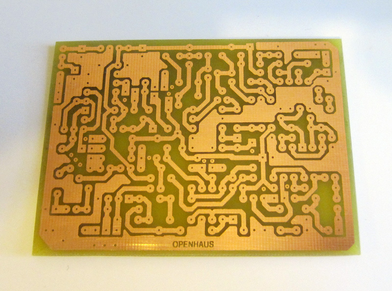
the only question that I have is the "(D)" symbol near the top of the board? it looks like it would connect the +15V to ground so is it a diode for protection?
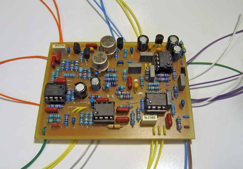
after building Harald Sabro's vero layout over a year ago and it works perfectly. I just built another one for a friend using dimebugg's layout.
one thing to note on dimebagg's PCB layout The 2LND150N3-G's pinouts are incorrect. they should be rotated 180 degrees and swap the gate and source leads. other than that it works perfectly.
here's a couple of pics of my current build's board:
Are you really sure of the Q2, Q5 and Q6 pinouts of dimebugg's pcb?? Did you verify it completely?
Because if I compare with Harald Sabro's vero (that is verified!), one should keep the orientations of all these Transistors but reverse G & S for all of them...
If I look very well at the vero layout:
- on Q2, G is connected to R19 (Vref), and S connected to R21; if you use the orientation of Dimebugg's layout (DSG from top to bottom), you have to cross S and G because LND150 are wired like this D-G-S.
- the same for Q5: S connected to R28 and G to R27 in the Sabro's Layout. On the Dimebugg's layout is written DSG (from top to bottom) and you have to cross S and G with the same orientation, to reach the D-G-S pinout.
- for Q6, I have found on Sabro's layout that G is connected to R30 and S to R29. Again the same problem: you have to keep the same orientation but cross G and S on the 2N5457 (pinout D-G-S again).
This layout is completely unclear to me!
Does anyone have really verified it, and if it is the case, can explain us how to wire these transistors??
Just wanted to share my shitty clone with you. It surely needs additional polishing and new label plate, but i'll leave it like this until, you know, better times...
Huge thanks to all of you who helped to trace and make a layout, especially Dimebugg.
Despite some tweaking (jfet pinout) and rare parts (that ofcourse could be substituted), i found it quite easy to build.
Any suggestions how to modify it to add a little more presence? It feels kind of strange, more "closed" than otherpedals. The sound seems to be somewhere "there", not "here". As if the sound source is located in the other room, but not in front of you.
johnk wrote:after building Harald Sabro's vero layout over a year ago and it works perfectly. I just built another one for a friend using dimebugg's layout.
one thing to note on dimebagg's PCB layout The 2LND150N3-G's pinouts is incorrect. they should be rotated 180 degrees and swap the gate and source leads. other than that it works perfectly.
here's a couple of pics of my current build's board:
I'm sure you know this but the lead's of germanium transistors are not left long just for mojo appearance. There extremely sensitive to heat and that's why its recommended you don't solder your germanium transistors like that I'm sure you've forgotten more than I know however haha
Success is no accident. It is hard work, perseverance, learning, studying, sacrifice and most of all, love of what you are doing or learning to do.
johnk wrote:well, i haven't had a single issue soldering them in like that.
yah I'm literally just puking back info I've read, can't say I've ever had an issue with it either but I switched up just because of how expensive some are getting. I don't wanna take the risk even
Success is no accident. It is hard work, perseverance, learning, studying, sacrifice and most of all, love of what you are doing or learning to do.
Hello! I'm about to make this high-gain beast, but I'm not clear on what the wiring is like, is there a reference nomenclature for the letters where the cables go? https://ibb.co/dtVh7p
Thank you very much in advance!!!!


