Let's try to trace this
This pedal came on a mini mini bomb, which was based on a single JFET transistor
The mini bomb schemaешс is presented below
As well 2 transistors in a pair (something similar to mu-amp)
In the Ruby Red & Kilt pedals, a new booster is also being used (which is similar to the components with the Prestige stuffing).
JHS describes this as a 2-stage booster.
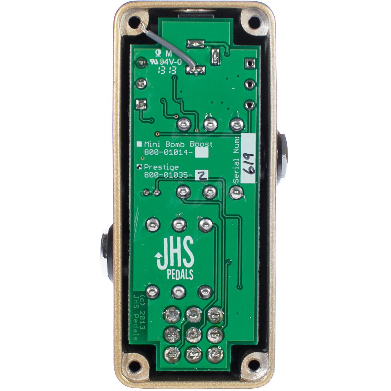
Guts
Maybe someone has a Prestige and he will share photos of guts in HD
Link to JHS Kilt, there is HD photo and booster inside
https://www.freestompboxes.org/download/ ... &mode=view