Hello,
at least, after Hundreds of Years of research (aprox.) I found some Picture of the Backside from the Original Schaller GE Fuzz.
made some PCB tracing with Target3001 (E-Cad like Eagle) try to get it in here.
It`s just possible to make some pdf but no jpeg or something.
Maybe someone in here will help to finish the layout (just finished the tracing right now)
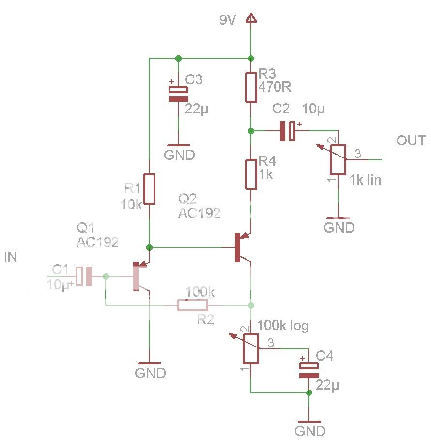
Schaller - Fuzz (Germanium) [schematic]
Oh, and i forgot:
the space between the Copper traces is around 1mm (all Measures in mm) just cut in, maybe milled with a thin
milling cutter, i will try try it with a dremel cutting wheel.
All very straight what makes me think it was on a milling machine (not per hand)
And be aware: there are some different layouts out of this time, i saw one with all legs of transistor 1 pulled through one big hole- for example.
 SchallerGE_Fuzz_Front_Layout.PDF
- (9.42 KiB) Downloaded 627 times
Ok, some explanations:
the 100K from Q2 Emitter to Q1 Base (the angular one) goes through the holes from the Transistors legs.
The 1k (yes) Collector R covers the holes from Base and Emitter of Q2 (Q1 is left Q2 is right, sorry will make a nicer one soon )
)
The "Intensität" Pot (love this word ) is one side on Ground other side is on Q2 Emitter trace, mid (wiper)lug is wired to C on the far right upper lug (this one not on ground) and builds the emitter 2 Resistor( i think its a very common 1K lin, tried it and worked and sounded right)
Input is upper left corner on the Cap.
The pots are already unknown but "Intensität" has to be 1k i think, 100K for Volume works fine, i went down to 5k worked fine to. ther is only some little differents in highs (very little) not in bass due to the big output Cap (10µF). maybe someone here can help and solve the mystic about these pots
completed and corrected the "Raw" layout (C_Out was flipped)
the 100K from Q2 Emitter to Q1 Base (the angular one) goes through the holes from the Transistors legs.
The 1k (yes) Collector R covers the holes from Base and Emitter of Q2 (Q1 is left Q2 is right, sorry will make a nicer one soon
The "Intensität" Pot (love this word
Input is upper left corner on the Cap.
The pots are already unknown but "Intensität" has to be 1k i think, 100K for Volume works fine, i went down to 5k worked fine to. ther is only some little differents in highs (very little) not in bass due to the big output Cap (10µF). maybe someone here can help and solve the mystic about these pots
completed and corrected the "Raw" layout (C_Out was flipped)
- SchallerGE_Fuzz_Layout_PCB.PDF
- (15.81 KiB) Downloaded 411 times
-
Manfred

- Tube Twister
Information
- Posts: 1944
- Joined: 04 Apr 2009, 23:42
- Has thanked: 1675 times
- Been thanked: 1360 times
I found this schematic:
-
Manfred
- Tube Twister
Information
- Posts: 1944
- Joined: 04 Apr 2009, 23:42
- Has thanked: 1675 times
- Been thanked: 1360 times
On the schematic of the previous post, the connections of Emitter and Collector have been interchanged.
-
Manfred
- Tube Twister
Information
- Posts: 1944
- Joined: 04 Apr 2009, 23:42
- Has thanked: 1675 times
- Been thanked: 1360 times
The edit function did not work twice, Here's a supplement to the previous post.
the values of the potentiometer values have been interchanged too.
the values of the potentiometer values have been interchanged too.
-
Manfred
- Tube Twister
Information
- Posts: 1944
- Joined: 04 Apr 2009, 23:42
- Has thanked: 1675 times
- Been thanked: 1360 times
Corrected Schematic:
I´ve seen this schematic too but its completly wrong there is also just one other schemo getting around thats full of guesses.
(But you did it "Manfred" you got it right)
(But you did it "Manfred"
but it was just a short transfer time they used AC192 (between the Ge and Si ones), from beginning they used AC151r
Hi Guys,
I actually own this pedal. It's the heavy ' metal' enclosure with the AC192. I looked at the schematic above and have looked at my pedal (which looks like its still original) for my values. These seem to vary a bit from yours. Maybe they did different versions..
I actually own this pedal. It's the heavy ' metal' enclosure with the AC192. I looked at the schematic above and have looked at my pedal (which looks like its still original) for my values. These seem to vary a bit from yours. Maybe they did different versions..
- Attachments
-
note: The extra 25uF was soldered in afterwards.. although it's actually the same brand and time period. It seems legit and also done by the company itself. Therefore the 'PCB' design is the same for my pedal.
-
Manfred
- Tube Twister
Information
- Posts: 1944
- Joined: 04 Apr 2009, 23:42
- Has thanked: 1675 times
- Been thanked: 1360 times
Cool! another ' mystery' solved 
Wow guys,
i had alook from time to time in web and wondered for years, that there`s no Schematic/Tracing from this Fuzz before.
This is really a historic Moment!!!!!!!
Thank you Guys for sharing this with me.
By the way: I found this is one of the best sounding (Vintage)Fuzzes build, love the Sound and it´s much more versatile and useful than a Fuzzface.
Thank you FUZZZzzzz for completing it and thanks Manfred for your help.
Wow
I also did a little exercise. Can probably be smaller, but I like to build things easy. Yet unverified!
- Attachments
-