How would i go about doing this? I was looking at the modulation circuits for the 2399 chips, but that chip uses a different method for determining delay time, and at the very least it won't go straight into this Dan-Echo as drawn.
I am too much of a noob to know what to do with this one guys.
Attached are the application notes for the PT2395, the general chip overview(which has a clearer image of the application circuit in it), and the PT2399-style modulation schematic.
If not a modification to the "delay time" part of the circuit, would it be possible to apply the LFO circuit to the input voltage? Slight fluctuations in this voltage have a distinct speed/pitch influence on the signal, so if anyone could point me in the direction of hooking that up, it might work as well?
Thanks for whatever thoughts you've got!
-chris
Danelectro - Dan-Echo: adding modulation to PT2395 delay
-
chris_d

- Solder Soldier
- Attachments
-
-
 PT2395 Application Notes.pdf
- (518.96 KiB) Downloaded 375 times
-
- PT2395 Delay Chip.pdf
- (262.79 KiB) Downloaded 319 times
-
chris_d
- Solder Soldier
I posted this at diystompboxes too, but here it is again for anyone here who might be interested.
O.k. I figured something out. It works putting the LFO in series with the battery, but it works *better* putting it in series with the delay time pot.
Basically i just took the PT2399 modulation circuit, kept the original "in", but instead of the "depth" control having the input on one end and ground on the other, i just swapped the ground for the output.
The values i am using are probably too high for this to be a very subtle modulation effect, but with my danecho messings, subtlety is not often much of an aim for me.
So as it stands now, i have done the following:
1. Got rid of R10, replaced with a jumper, to allow the delay to self-oscillate. The Danecho should ship from the factory like this, IMO.
2. Swapped the 5k-L delay time pot for a 50K. This allows the really stupidly long delay times, something like eight or nine seconds maxed out with the switch set to "long". The quality of the repeats is pretty much crap at anything much longer than the longest stock setting, but some very cool effects can be had with the cruddy super-long repeats as well. It also allows a really nice super deep sweep when the thing is oscillating.
3. Added an LFO circuit in series with the delay time pot for some sort of modulation ability. Like i said, the values i used make it difficult to get subtlety from this effect, but it is still cool to have. It adds an interesting synth-like sound to the delay too, like a combination of chorusing and pitch wheel at high "depth" settings.
So far i have just messed with it direct into my soundcard. Tomorrow i will use it with an amp and be able to see what i actually have here! My initial impressions are that what i have done is added some really wild noisemaking abilities to this pedal, but that i can still dial in the original echo sounds, as well, as long as i am pretty careful/precise adjusting the much bigger value delay time control. I am actually thinking that a 50k-A pot might be a better choice for this than the linear one. Most of the "usable" delay times seem to live between about 7:00 and 9:30 or so right now with the linear taper.
Anyhow, just thought i would share, in case anyone else has one of these pedals and maybe wasn't happy with it as is, or is just looking, as i was, to make it more of a noisemaker.
Oh, the only problem i have now, is that there really is no way i can fit the modulation board into the pedal. Actually, my 50k delay time pot doesn't fit either:

:icon_lol: Looks like i will be reboxing it. Hopefully by the time i do that i will have learned enough about switching and buffers to be able to true-bypass the thing as well. The bypass on this thing does suck.
Anyhow, that's it for now.
-chris
O.k. I figured something out. It works putting the LFO in series with the battery, but it works *better* putting it in series with the delay time pot.
Basically i just took the PT2399 modulation circuit, kept the original "in", but instead of the "depth" control having the input on one end and ground on the other, i just swapped the ground for the output.
The values i am using are probably too high for this to be a very subtle modulation effect, but with my danecho messings, subtlety is not often much of an aim for me.
So as it stands now, i have done the following:
1. Got rid of R10, replaced with a jumper, to allow the delay to self-oscillate. The Danecho should ship from the factory like this, IMO.
2. Swapped the 5k-L delay time pot for a 50K. This allows the really stupidly long delay times, something like eight or nine seconds maxed out with the switch set to "long". The quality of the repeats is pretty much crap at anything much longer than the longest stock setting, but some very cool effects can be had with the cruddy super-long repeats as well. It also allows a really nice super deep sweep when the thing is oscillating.
3. Added an LFO circuit in series with the delay time pot for some sort of modulation ability. Like i said, the values i used make it difficult to get subtlety from this effect, but it is still cool to have. It adds an interesting synth-like sound to the delay too, like a combination of chorusing and pitch wheel at high "depth" settings.
So far i have just messed with it direct into my soundcard. Tomorrow i will use it with an amp and be able to see what i actually have here!
Anyhow, just thought i would share, in case anyone else has one of these pedals and maybe wasn't happy with it as is, or is just looking, as i was, to make it more of a noisemaker.
Oh, the only problem i have now, is that there really is no way i can fit the modulation board into the pedal. Actually, my 50k delay time pot doesn't fit either:
:icon_lol: Looks like i will be reboxing it. Hopefully by the time i do that i will have learned enough about switching and buffers to be able to true-bypass the thing as well. The bypass on this thing does suck.
Anyhow, that's it for now.
-chris
-
chris_d
- Solder Soldier
-
seniorLoco

- Resistor Ronker
looks cool like that ...
Btw nice clips there ...
"Curiosity may have killed the cat, but it saved the mice, who ate the cheese."
-
chris_d
- Solder Soldier
Yeah, i thought it looked cool too, but i was afraid the vero board would bounce around short out on the input/output plugs, also i had to resolder a couple of connections because of all of the movement from it just floating like that.seniorLoco wrote:looks cool like that ...
So i gave it one more go at making it fit, and it did, just barely:

If i were to do it again i would do it differently, and mount the pots on the opposite side, where the battery normally goes. This one works best with a nice steady wall wart power supply anyhow. Batteries don't last long, and when they die, the bypass gets even worse than it normally is. So losing the battery space is really not a big deal.
I definitely like the pedal a lot more now. But i absolutely have to get back in there and find a way around that shitty bypass. Otherwise i am going to have to build a true bypass loop box just for this pedal.
-chris
Hey Chris, for the bypass issue you could try something like what I did to my rebote delay, I'm not familiar with the topology of your effect, but if it applies I recommend it a lot.
Check out this thread;
viewtopic.php?f=10&t=3072&p=34850#p34850
Check out this thread;
viewtopic.php?f=10&t=3072&p=34850#p34850
The Freestompboxes Forum search function is soo great, use the search function..., the S E A R C H function.
-
Uma Floresta

- Breadboard Brother
I have a Dan-Echo in the mail. I'll definitely jumper R10 (and do that "harp" input impedance mod, if necessary). I don't know that I have a use for modulation or super long delay time, but thanks for doing such extensive work on this 
The paintless enclosure looks really cool.
The paintless enclosure looks really cool.
-
chris_d
- Solder Soldier
I use the delay for ambient noise as much as subtle delay so both the delay time and the modulation are very interesting to me. For "normal" delay use, i would probably leave the delay time as is(much longer than stock and the repeats are really lo-fi) but possibly consider the modulation. The mod circuit is very simple, and you could just add it at first as i did, externally, just to experiment with it if you wanted to.Uma Floresta wrote:I have a Dan-Echo in the mail. I'll definitely jumper R10 (and do that "harp" input impedance mod, if necessary). I don't know that I have a use for modulation or super long delay time, but thanks for doing such extensive work on this
The paintless enclosure looks really cool.
What is nice about the modulation, is that on shallower settings, you can actually get a sound that is sort of between a flanger and a chorus. As i have really no use for a dedicated chorus pedal, it is nice to at least have the option built into the delay.
Anyhow, i was bored, so i have since taken the cream-color plastic bit off and painted it hammertone dark grey so it looks like this now:

-chris
-
Uma Floresta
- Breadboard Brother
Interesting. Would the LFO pcb fit in the battery compartment? I never use batteries, anyway.chris_d wrote:I use the delay for ambient noise as much as subtle delay so both the delay time and the modulation are very interesting to me. For "normal" delay use, i would probably leave the delay time as is(much longer than stock and the repeats are really lo-fi) but possibly consider the modulation. The mod circuit is very simple, and you could just add it at first as i did, externally, just to experiment with it if you wanted to.Uma Floresta wrote:I have a Dan-Echo in the mail. I'll definitely jumper R10 (and do that "harp" input impedance mod, if necessary). I don't know that I have a use for modulation or super long delay time, but thanks for doing such extensive work on this
The paintless enclosure looks really cool.
What is nice about the modulation, is that on shallower settings, you can actually get a sound that is sort of between a flanger and a chorus. As i have really no use for a dedicated chorus pedal, it is nice to at least have the option built into the delay.
Anyhow, i was bored, so i have since taken the cream-color plastic bit off and painted it hammertone dark grey so it looks like this now:
-chris
-
Uma Floresta
- Breadboard Brother
and a follow-up question - was it necessary to isolate the LFO circuit from the main power supply?
-
chris_d
- Solder Soldier
I did not do so. In fact i just tacked the LFO's power and ground wires right to the back of the danecho's. Basically on the input board the power comes in at 9v and then goes through a regulator that brings it down to about 5v, which is then sent on a ribbon cable to the main board. I just tapped off where it was still 9v for the LFO. Maybe this isolates the two parts of the circuit enough that noise isn't so much of an issue? Honestly i am too much of a noob to know without doing some more reading!Uma Floresta wrote:and a follow-up question - was it necessary to isolate the LFO circuit from the main power supply?
If you exercise care in laying out the LFO circuit you could easily fit it in the battery spot. If i were to do it again, i would do it that way actually. The vero layout i did was more the product of neccesity than anything else, as that was the last piece of vero board i had left, so i had to lay the circuit out to fit the board i had, rather than the other way around. I just happened to get "lucky" in that the board dimensions were fairly well suited to the space i chose to utilize. Using the battery space would probably be much more straightforward though.
-chris
-
Uma Floresta
- Breadboard Brother
Thanks again for your help. Maybe I will add modulation. Your soundclips are very cool 
-
modman

- a d m i n
Information
- Posts: 4897
- Joined: 19 Jun 2007, 16:57
- Has thanked: 4410 times
- Been thanked: 2139 times
Nice documentation, Chris, moved and retitled to save you from having to type in once more.
If you want to share valuable info like this, don't hesistate to use the attachment function, external links might die out eventually.
moved to 'Pimp My Cheapo'
Please, support freestompboxes.org on Patreon for just 1 pcb per year! Or donate directly through PayPal
-
chris_d
- Solder Soldier
Cool, i will keep that in mind for the future!modman wrote:
Nice documentation, Chris, moved and retitled to save you from having to type in once more.
If you want to share valuable info like this, don't hesitate to use the attachment function, external links might die out eventually.
moved to 'Pimp My Cheapo'
-chris
-
Uma Floresta
- Breadboard Brother
Well, I removed R10 - definite improvement. The self-oscillation is pretty lo-fi as these things go, but it's nice to have it there.
-
puppiesonacid
- Cap Cooler
wow! very cool and useful mods. thanks
-
chris_d
- Solder Soldier
Oh, and i thought i already posted this, but i guess not. For folks who would rather see something in schematic form than a written description, this is what the PT2399 modulation circuit looks like modified for the PT2395 chip, as i utilized it:
-chris
-chris
- Attachments
-
- Modified modulation circuit for PT2395 application.
-
Uma Floresta
- Breadboard Brother
Some clips I made after jumpering R10:
Infinite repeats:
http://soundclick.com/share?songid=6925955
Self-Oscillation:
http://soundclick.com/share?songid=6925935
This is a great little delay pedal.
You know, I was thinking, if you had a switch to defeat the dry signal, this would be a poor man's Pitch Pirate, with those extreme LFO settings.
-
harpplayer
Information
Hi! My name is André, from Brazil, and I´ve just joined the forum.
I see that this topic is a bit old, but having just bought a Dan Echo, I couldn´t help myself from trying to restart it:P
Has anyone done that really nice mod and would be kind enough to help me?
I did the r10 mod already, with a switch to go back to the stock stomp.
I understand basic schematics, but I got a little confused with the LFO one, as it seemed a little different from the pictures posted (plus I am not sure which OP amp was used). Someone maybe had put that into simple layout and would like to share?
Thanks very much!
André
-
chris_d
- Solder Soldier
Harpplayer, i am sorry i missed your post somehow!
By now, i would guess that you figured something out, but if someone else is seeking a simple vero layout for the LFO circuit, i have this one which i just found on an old hard drive:
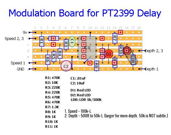
Now, it does come with some caveats.
I made this pretty quick and dirty, and a long time ago. Because i made it for my own use, it may not be as clear as might be desirable on some points, such as how the LED/LDR is drawn. The trace cut at B4 is obscuring the label "R2" i believe, the ones at D12 and E12 are obscuring the label for "R9", and the cut at F14 is obscuring the label for "R11".
Actually, when i built it, i also was very concerned that i would not have room for it, so the board i have in my dan-echo is actually shortened by four holes, and it was a little sketchy to do that, so i won't post the layout for it. The layout above should fit though, especially if you put it in the battery's spot.
Also, pay attention to the trace cut that sits underneath the LED for the LED/LDR. The rest should be obvious and easy to read though, i think.
Other than that, i *think* the layout should be fine as drawn, and i am pretty sure that my build worked correctly right out of the gate. That was a while ago, but i don't have any note here indicating that i had any trouble with that part of the build.
Hopefully this will be of some use to someone, anyhow. :idk:
Any questions, or comments to point out errors or problems or whatever are welcome.
-chris
By now, i would guess that you figured something out, but if someone else is seeking a simple vero layout for the LFO circuit, i have this one which i just found on an old hard drive:
Now, it does come with some caveats.
I made this pretty quick and dirty, and a long time ago. Because i made it for my own use, it may not be as clear as might be desirable on some points, such as how the LED/LDR is drawn. The trace cut at B4 is obscuring the label "R2" i believe, the ones at D12 and E12 are obscuring the label for "R9", and the cut at F14 is obscuring the label for "R11".
Actually, when i built it, i also was very concerned that i would not have room for it, so the board i have in my dan-echo is actually shortened by four holes, and it was a little sketchy to do that, so i won't post the layout for it. The layout above should fit though, especially if you put it in the battery's spot.
Also, pay attention to the trace cut that sits underneath the LED for the LED/LDR. The rest should be obvious and easy to read though, i think.
Other than that, i *think* the layout should be fine as drawn, and i am pretty sure that my build worked correctly right out of the gate. That was a while ago, but i don't have any note here indicating that i had any trouble with that part of the build.
Hopefully this will be of some use to someone, anyhow. :idk:
Any questions, or comments to point out errors or problems or whatever are welcome.
-chris