Danelectro - Rocky Road In/Out Board - What's Going On?
Hi, I've recently completed a Chicken Salad re-house with info posted here from you kind folks on this board.
I'm about to attempt the same with a Rocky Road. I found this schematic for the In/Out board. I'm having trouble understanding what's going on, there appear to be two signal inputs going to the main board connector and two returns.
Here's the schematic - I'd be really grateful if someone could shed some light on what's happening on pins 2&3 and pins 6&7 - thanks!!
- andre
- Breadboard Brother
Information
- Posts: 51
- Joined: 21 Jan 2008, 15:20
- my favorite amplifier: Hughes & Kettner Statesman Quad
- Completed builds: Dist + overdr.: Distortion+, BSIABII, Shaka III, Bluesbreaker, Box of Rock, Highway 89, DS-1, Proce Rat, Omnidrive, TS808, Bluemagic, Fulldrive 2, big muff
Delay: DM-2, Rebote 2.5, PT-80
Modulation: Ross Phaser, Small Clone, CE-2, Zombie chorus, FL-301, Easyvibe, Ultraflanger
Compr.: Dod280, Dynacomp
the rest: SG-1, Sparkleboost, BAJA CX-3 leslie simulator - Location: Netherlands
- Been thanked: 6 times
Since I'm the one that drew that schematic, I guess I will have to answer your question too
pin 2 is sound output from the mainboard.
pin 3 is sound input to the mainboard.
pin 6 controls the FET that switches the input signal to the output. (Bypass mode)
pin 7 controls the FET that switches the effect signal to the output (Effect on)
André
pin 2 is sound output from the mainboard.
pin 3 is sound input to the mainboard.
pin 6 controls the FET that switches the input signal to the output. (Bypass mode)
pin 7 controls the FET that switches the effect signal to the output (Effect on)
André
Thank you! Is and thank you again for the drawing!!
André - if I may impose again.... Since I will be doing away with the in/out board and using a 3PDT true bypass I presume I can ignore pins 6 and 7?
I'll have to use the 5v regulator - what does it do on the main board?
Thanks.
I'll have to use the 5v regulator - what does it do on the main board?
Thanks.
- andre
- Breadboard Brother
Information
- Posts: 51
- Joined: 21 Jan 2008, 15:20
- my favorite amplifier: Hughes & Kettner Statesman Quad
- Completed builds: Dist + overdr.: Distortion+, BSIABII, Shaka III, Bluesbreaker, Box of Rock, Highway 89, DS-1, Proce Rat, Omnidrive, TS808, Bluemagic, Fulldrive 2, big muff
Delay: DM-2, Rebote 2.5, PT-80
Modulation: Ross Phaser, Small Clone, CE-2, Zombie chorus, FL-301, Easyvibe, Ultraflanger
Compr.: Dod280, Dynacomp
the rest: SG-1, Sparkleboost, BAJA CX-3 leslie simulator - Location: Netherlands
- Been thanked: 6 times
Yes, you can ignore pins 6 & 7.Since I will be doing away with the in/out board and using a 3PDT true bypass I presume I can ignore pins 6 and 7?
Although I was able to trace the input/output board, the mainboard is too complex to trace,I'll have to use the 5v regulator - what does it do on the main board?
so I can't tell you what the 5V is used for.
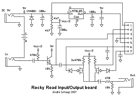
Here's the schematic of my new Input/Outputboard:
I also made a PCB for this circuit, but I can't find it right now.
I will post it as soon as I found it.
You could of course also choose to keep the original Input/Output board and remove the unused parts
and modify it to my new Input/Output board.
Please report back your progress because I still have to rehouse my RockyRoad and any idea is welcome.
André
Thanks again André, I'll keep you posted.
I just won the Rocky Road on eBay this afternoon so it'll be a few days before I can get started.
- andre
- Breadboard Brother
Information
- Posts: 51
- Joined: 21 Jan 2008, 15:20
- my favorite amplifier: Hughes & Kettner Statesman Quad
- Completed builds: Dist + overdr.: Distortion+, BSIABII, Shaka III, Bluesbreaker, Box of Rock, Highway 89, DS-1, Proce Rat, Omnidrive, TS808, Bluemagic, Fulldrive 2, big muff
Delay: DM-2, Rebote 2.5, PT-80
Modulation: Ross Phaser, Small Clone, CE-2, Zombie chorus, FL-301, Easyvibe, Ultraflanger
Compr.: Dod280, Dynacomp
the rest: SG-1, Sparkleboost, BAJA CX-3 leslie simulator - Location: Netherlands
- Been thanked: 6 times
Here's the PCB and partslayout for my new In/out board:
Most parts including the connector J1 could be salvaged from the original In/Out board.
If you print the PCB at 300dpi it should print the right size which is 3.2 cm x 2.8 cm.
Although not verified, I believe the PCB is correct.
I built one last night but I won't be able to test it for the next couple of days.
After that I will try to find a way to automatically switch on the effect on powerup
André
depends on what your goal is.... do you want to remove the stuff you don't need, or do you not care and just want to true bypass....
- John G
- Breadboard Brother
Hi all,
I have just picked up a Rocky Road pedal and will do the unity gain mod, but I am still perplexed as to why when the Drive control is advanced there is a huge increase in volume before the distortion kicks in and there is no control to adjust the vol back to unity.
I must admit it sounds more like the real thing with the distortion up (colour) but has this level disparity.
Mine could be faulty ?? but if not can someone enlighten me as to why you would want such an increase in practice.
Looking at the schematic I can see the possibilty to add a level control in place of the 100k resitor to ground after the clipping diodes.
Thanks for any help you can give me.
John
- ChristoMephisto
- Breadboard Brother
Information
- Posts: 50
- Joined: 09 Jun 2008, 22:51
The RR has a pair of LEDs set to hard clipping, Dano wanted to give it some tube amp sound, giving it lot of headroom.John G wrote:Hi all,
I have just picked up a Rocky Road pedal and will do the unity gain mod, but I am still perplexed as to why when the Drive control is advanced there is a huge increase in volume before the distortion kicks in and there is no control to adjust the vol back to unity.
I must admit it sounds more like the real thing with the distortion up (colour) but has this level disparity.
Mine could be faulty ?? but if not can someone enlighten me as to why you would want such an increase in practice.
Looking at the schematic I can see the possibilty to add a level control in place of the 100k resitor to ground after the clipping diodes.
Thanks for any help you can give me.
John
Even after the unity mod, I still play with the drive off. You could change the clipping diodes to 1N4148 or 1N400x for lower headroom, possibly distortion.
Without the schems to the RR's effect board, can't offer you any more help
- John G
- Breadboard Brother
Hi,
Thanks for the reply, since my last post I have made some changes to the RR mainly because of the poor signal to noise ratio.
Sinse I was doing a rehouse and doing a true bypass and mounting external controls.
I decided to leave the R44 alone and instead add a o/p vol control at the output of IC5B and straight off to the bypass switch.(removed bluewire)
I now can get less than unity gain, as well as 3X gain and a better S/N .
I have installed some back-back 1N4148 diodes across the gain pot, removed R10 and intalled a 100K lg pot wired as a variable resistor to ground and is now switched in with an additional switch now marked distortion on/off.
So I now have an over all vol control, f/sw distortion with gain and its own level.
PS I removed R10 to reduce treble boost.
- John G
- Breadboard Brother
Silver,
I use two fine pointed soldering irons at each end of the component to remove it.
You could use fine tweezers to grip the body and apply the iron to one end and then the other quickly.
To insert the component the pads need to be clean and flat, I usually use a spot of contact glue to hold it in place when resoldering.
I believe that the parameters of speed an ramp times are set within the chip........lookup the chip manufactures specs there may be some info given that will alow you to make ajustments.
John
Hi John!
I did the unity gain and treable mod (easily removed the R26),but still is a bit louder than the bypass signal.Can you show me how to install that vol pot you mentioned in previuos post (from the IC5B)?
Thanks
P.S. Rocky Road is very similar (soundwise) to Vibratone,but there is a lot of tweaking needed to get it work for the purpose it was designed.