hi, my first post in this great forum!
I'm looking for some circuit pics of Bixonic's expandora, I found nothing so maybe you've that ?
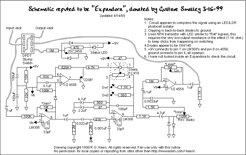
Also, you think this schemo is correct ?
http://www.geofex.com/FX_images/expandor.gif
thanks!
-Devastator-
Bixonic - Expandora [traced]
-
devastator

- Cap Cooler
-
soulsonic

- Old Solderhand
Information
I have an original Bixonic Expandora. I haven't had a chance to open it up yet to verify Gus' schematic. Gus knows what he's doing, so I'm sure his schematic is correct, but still, it's nice to have photos to prove it. If I get a chance, I will try opening it up to verify and take pictures. I recall last time I looked in it, I was confused about how to remove the board because of how it's held in with the I/O jacks... anyone else here know what I'm talking about?
"Analog electronics in music is dead. Analog effects pedal design is a dead art." - Fran
-
analogguru

- Old Solderhand
Information
analogguru
There´s a sucker born every minute - and too many of them end up in the bootweak pedal biz.
-
soulsonic
- Old Solderhand
Information
Yes, it looks exactly like that. I can't figure out how to remove the board. There's no room to slide the jacks out of the case mounting holes. It was very strange to me. I need to look at it again and see if there's something I missed.
"Analog electronics in music is dead. Analog effects pedal design is a dead art." - Fran
-
soulsonic
- Old Solderhand
Information
I suppose so. I don't understand why they would build it that way; but looking at it, I can see how the jacks may have been installed first, and then the board soldered to them.lynessmy wrote:I guess you need to desolder the jack before can take out the PCB....
"Analog electronics in music is dead. Analog effects pedal design is a dead art." - Fran
-
Dirk_Hendrik

- Old Solderhand
Information
soulsonic wrote: I suppose so. I don't understand why they would build it that way
Easy and cheaper construction. Saves the time to strip and solder wires and holds the board in place at the same time. Provided there's a proper mechanical strain relief on the jacks, so no tension on the solder joints when inserting a plug, there's nothing wrong with that construction. Tech21, as an example, does the same.
-
guiltyspark
- Solder Soldier
I had the same problem. A while back I was thinking of modding one for more low end but couldn't get the board out. Figured out the jacks have to come off and it looked like a hassle so I moved on. I kind of like the basic tone but they always seemed a little thin sounding to me.soulsonic wrote:Yes, it looks exactly like that. I can't figure out how to remove the board. There's no room to slide the jacks out of the case mounting holes. It was very strange to me. I need to look at it again and see if there's something I missed.
Guiltyspark
-
soulsonic
- Old Solderhand
Information
The thing that always bothered me was how mushy it is at high-gain settings. At low drive settings, I think it sounds great, but at high gain, everything just splats out. It would be nice to see if that could be tamed a little bit.
"Analog electronics in music is dead. Analog effects pedal design is a dead art." - Fran
A friend had one that they needed that same day. I only had a few hours to fix it and trace it so the schematic might have an error(s). (dirty contact(s)IIRC). I unsoldered. the jacks to remove the board. IIRC the board is a quality one so if your unsoldering skills are good you should have no problem with the pads
-
modman

- a d m i n
Information
- Posts: 4897
- Joined: 19 Jun 2007, 16:57
- Has thanked: 4410 times
- Been thanked: 2139 times
But the internet doesn't, and eats the reservations that accompanied the drawing initially. It would be very nice if we could set the record straight on this one... when you get around to it, Soulsonicsoulsonic wrote:I have an original Bixonic Expandora. I haven't had a chance to open it up yet to verify Gus' schematic. Gus knows what he's doing
Please, support freestompboxes.org on Patreon for just 1 pcb per year! Or donate directly through PayPal
-
Whoismarykelly
- Resistor Ronker
Seriously guys? The unrelenting clone train that is FSB.org is being ground to a halt by some jacks that are soldered to the board? Screw goop. Why isn't everyone else just using board mounted jacks?
-
Dirk_Hendrik
- Old Solderhand
Information
If that seems to be the case to you. So be it. No problem. Byebye.Whoismarykelly wrote:Seriously guys? The unrelenting clone train that is FSB.org is being ground to a halt by some jacks that are soldered to the board?
Information
- Posts: 14
- Joined: 13 Jun 2008, 04:59
... I think he was joking....Dirk_Hendrik wrote:If that seems to be the case to you. So be it. No problem. Byebye.Whoismarykelly wrote:Seriously guys? The unrelenting clone train that is FSB.org is being ground to a halt by some jacks that are soldered to the board?
-
Whoismarykelly
- Resistor Ronker
I was indeed. I mean, it is funny though that the same guys that can chip away at goop for hours on end wont desolder some jacks to get into a pedal.eleanor296 wrote:... I think he was joking....Dirk_Hendrik wrote:If that seems to be the case to you. So be it. No problem. Byebye.Whoismarykelly wrote:Seriously guys? The unrelenting clone train that is FSB.org is being ground to a halt by some jacks that are soldered to the board?
-
soulsonic
- Old Solderhand
Information
Well, I finally took the time to tear it apart.
Initial inspection looks like Gus' original schematic is right on. So far the only thing I've seen different is a diode marked as a "?" in the scheme is a Zener.
- Bixonic Expandora
"Analog electronics in music is dead. Analog effects pedal design is a dead art." - Fran
-
sevinisthenumber

- Cap Cooler
Anyone know any mods for this unit?
"The man who says he knows everything will never know the truth"
C.S. Lewis
C.S. Lewis
Of all the 100's of distortion pedals i have bought and sold this is the one I regret.The distortion and forbidden settings are awesome.
I sold it becaucse of a loud pop I got when engaging the pedal. It drove me nuts. This was before True bypass loopers were popluar. I spoke with many owners an I was the only guy that had that problem.
They werent all like that one. I need to find another or get a clone thats not in a can and is handwired...
Actually that's a very good and reliable way (maybe the only way) to allow PCB mount jacks that also fasten to opposite sides of a case. If you bolt down the jacks then solder them to the PCB, you can eliminate strain on the solder joints that can cause joint failure in the future. If you solder the jacks on the PCB then bolt them into the case, the solder joints on the jack will be under a lot of strain.soulsonic wrote:I suppose so. I don't understand why they would build it that way; but looking at it, I can see how the jacks may have been installed first, and then the board soldered to them.lynessmy wrote:I guess you need to desolder the jack before can take out the PCB....
I breadboarded one of these from the internet schematic a few years ago, it is a very clever design. The main tweak is an expander circuit that allows higher amounts of drive when you hit the strings hard, and lower amounts with light picking. It exaggerates your picking style. Very cool.
-
soulsonic
- Old Solderhand
Information
Anyone ever find one of those Sharp optos? It's an optocoupler that uses a JFET. I found the datasheet, but so far I haven't found any substitutes with the same resistance range. 

I wonder what the new Expandoras use?
I wonder what the new Expandoras use?
"Analog electronics in music is dead. Analog effects pedal design is a dead art." - Fran