
FWIW - I've built the BYOC version, and assuming it's an accurate clone... it's VERY scooped, and pretty trebley and sort of transistory, metallic sounding.
The BYOC version has switchable EQ, but it still doesn't sound as good as a good Muff IMO.
Not something that appeals to me.
I wonder if it's reputation isn't built more on rarity than good tone.
Way Huge - Swollen Pickle
-
bumblebee

- Diode Debunker
just listening to the demos on the website of the SP mkII I like the sound of it, I'm actually gonna buy one soon.
I so dislike the modern digital world that I need to use semi-digital effects to emulate the analog world of cassette, VHS, and vinyl.
-
SpencerPedals

- Solder Soldier
Hey I'm mostly a lurker here since I am new to this (just built my first pedal, an Uglyface) but I was wondering if anyone had done a vero layout or PCB for this at all. I have a BYOC beaver so I have a regular muff sound and was looking to build this and a Dreamer for some scoopy variants. Anyway...just wondering if that existed...and hi! 
Steve
Steve
-
Dr Tony Balls

- Diode Debunker
Anyone have any clue what the added small control and trimpots are on the Mark II version of this (dunlop reissue)???
My initialy thought is that they just made some of the resistors in the tone stack variable, but I could be wrong.
My initialy thought is that they just made some of the resistors in the tone stack variable, but I could be wrong.
-
Solidhex
- Resistor Ronker
I noticed on the diagram of the transistor array shown here: http://happybob.com/marc/circuits/WayHuge/
That each transistor has a diode from base to emitter. Wouldn't those throw the bias off if using standard value Muff resistors in the circuit?
--Brad
That each transistor has a diode from base to emitter. Wouldn't those throw the bias off if using standard value Muff resistors in the circuit?
--Brad
-
Dr Tony Balls
- Diode Debunker
[quote="Solidhex"] I noticed on the diagram of the transistor array shown here: http://happybob.com/marc/circuits/WayHuge/
That each transistor has a diode from base to emitter. Wouldn't those throw the bias off if using standard value Muff resistors in the circuit?
--Brad [/quote]
Are you sure you arent misreading that? I dont see diodes b/w base and emitter, but i DO see that the not-so-conventional diagram shows a big triangle in the transistor symbol that makes it look like a diode.
-
RnFR
- Old Solderhand
Information
i see diodes from B to E in the array diagram. are you looking at the array diagram or the schematic?
"You've converted me to Cubic thinking. Where do I sign up for the newsletter? I need to learn more about how I can break free from ONEism Death Math." - Soulsonic
Blog-APOCALYPSE AUDIO
Blog-APOCALYPSE AUDIO
-
Solidhex
- Resistor Ronker
I'm talking about the diagram directly below the sentence: "The chip may be a 4-transistor array chip like an MPQ3904, which is a matched set of NPN transistors, so it could sound much like a vintage BMP..."
There's a diagram of a transistor array with 14 pins. You can see the collector, base, and emitter correspond with pins 1, 2, and 3. Each of the 4 transistors has a diode across the base and emitter. Cathode to base, anode to emitter...
-Brad
There's a diagram of a transistor array with 14 pins. You can see the collector, base, and emitter correspond with pins 1, 2, and 3. Each of the 4 transistors has a diode across the base and emitter. Cathode to base, anode to emitter...
-Brad
-
guiddruid
- Breadboard Brother
those diodes are reverse biased - they will do nothing unless the base voltage drops below the emitter = protection diode, probably as the transistor arrays can end up being used in H bridge driver circuits.
-
bumblebee
- Diode Debunker
Definitely diodes in this chip:

I so dislike the modern digital world that I need to use semi-digital effects to emulate the analog world of cassette, VHS, and vinyl.
-
guiddruid
- Breadboard Brother
...definitely reverse biased too. For one of those diodes to conduct, the base has to drop 0.6V below the emitter, which is connected via a resistor to gnd. Only place you could possibly get such a voltage would be on the first transistor, if you had an input signal of around 2 to 3 volts peak-to-peak. The diode would then limit the base to -0.6V, which would make no difference to the output from this stage - the transistor is already off. And you would be listening to some nasty (or possibly delightful - depends on your taste I guess) input stage clipping...
The diodes inside the transistor array do nothing in this circuit.
Scroll down the following page, until you see the diodes added to the circuit. Then think about the NPN transistor modeled as a couple of diodes with their anodes connected together. The diodes in the 4 transistor array allow you to make an hbridge for driving an inductive load, without requiring separate flyback diodes.:
http://www.dprg.org/tutorials/1998-04a/
-
tube-exorcist
- Resistor Ronker
The new one has a MPQ3904 inside.disorder wrote:Does anyone know if the Mark II is still just a Muff with transistor array?
"I've noticed there's an inverse relationship between cost of gear and talent. If you need the most expensive gear to get decent tones, then you suck as a player."
Gents, I Modified a black russian muff to the specs on that "muff in a pickle" schematic. I did it about a year ago and I believe I replaced the transistors to 2n5088's as well. When I was finished there was less gain than I expected and I have to have the volume control up fairly high to hit unity volume. Is this par for the course with this pedal, maybe a perceived reduction in volume due to the extreme scoop? I can also verify it sounding very mettalic and bright and transistor-y. Anyone who built can comment on output level. The gain also isn't terribly high ... But I'll admit I'm more of an amp distortion guy so I don't have much muff experience but I was expecting more gain. Thanks.
Joe
Joe
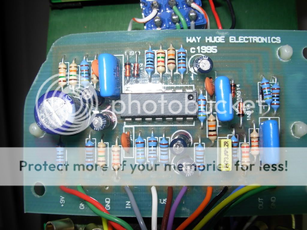
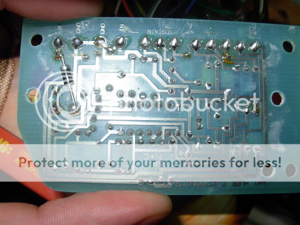
does anyone have a perfboard schematic for this kicking around anywhere? i started working on one but looking at the bottom im thinking there just may be too much going on there, then again im fresh at this. heres some guts as it seems this thread has been purged...
-
soggybag
- Resistor Ronker
Information
- Posts: 279
- Joined: 07 Aug 2007, 23:29
- Completed builds: Fuzz Face, Tone Bender, Big Muff, ICBM, Ugly Face, Green Ringer, Super Fuzz, Multiplex Echo, Multiplex Jr, Rebote, Echo Base, SHO, Fuzz Factory, Titan Boost/Octave, Easy Face, Tone Bender MkII, Trem Shifter, Zero Point Mini...
- Location: San Francisco
- Has thanked: 28 times
- Been thanked: 27 times
- Contact:
I built two of these a few years ago. It works pretty well. I forget where I ordered the chips, I just googled for them.
http://www.super-freq.com/?p=7
http://www.super-freq.com/?p=7
Blog: http://super-freq.com
-
bumblebee
- Diode Debunker
You can also use the 300P transistor array for this. That's what I'll be trying.
I so dislike the modern digital world that I need to use semi-digital effects to emulate the analog world of cassette, VHS, and vinyl.