hello people of the planet freestompbox..
i have a question how many amperage of the diode bridge if i use a transformer 220volts on primary and 15-0-15v on secondary and its a 6 ampere transformer??
the right diode bridge ampere
-
alexradium

- Resistor Ronker
25A
-
plush

- Cap Cooler
Your diode bridge power rating is defined mostly by how much power (current) your circuit draws from the transformer in peak. Extra power rating is good, but not always.ballfire wrote:hello people of the planet freestompbox..
i have a question how many amperage of the diode bridge if i use a transformer 220volts on primary and 15-0-15v on secondary and its a 6 ampere transformer??
Also there is no circuit protection implemented in your schematic. I suggest adding 2 fuses before your diode bridge (they will protect from both short circuit and diode rectifier failure). Fuses power rating must be defined according to your circuit power draw.
Also your schematic shows using zener diodes as power regulators. I myself'd replace them with linear voltage regulators with additional build'in protection.
-
Manfred
- Tube Twister
Information
- Posts: 1945
- Joined: 04 Apr 2009, 23:42
- Has thanked: 1675 times
- Been thanked: 1360 times
Hi ballfire,
download the Duncan PSU-Designer with it you can find all voltages and currents by simulation.
http://www.duncanamps.com/psud2/index.html
BTW the load is missing in your circuit it is required for correct results.
download the Duncan PSU-Designer with it you can find all voltages and currents by simulation.
http://www.duncanamps.com/psud2/index.html
BTW the load is missing in your circuit it is required for correct results.
-
george giblet
- Resistor Ronker
Firstly, do you realize for a 6A transformer you can only pull about 3.2A *average*? However, for a power amp the current is drawn from one half of the +V/-V supply at a time. Also, the supply current waveform is half-sinusoidal.
Anyway, if you have a transformer capable of 6A AC and you connect it up to a rectifier and filter, then pull the full load DC of 3.2A average off the DC rail (in your case what would be across +V and -V) then the peak current in the rectifiers will be in the order of 14A or so a 25A rectifier is a safe choice.
For a continuous load, the bridge rectifier will dissipate about 9W of heat. Which is a lot, and the rectifier will need a heatsink or will need to be mounted on the metal enclosure.
Smaller rectifiers will have higher diode drops and will get a little bit hotter.
-
george giblet
- Resistor Ronker
IIRC that should be 6W (Maybe if 6 was 9 it would correct.)For a continuous load, the bridge rectifier will dissipate about 9W of heat.
george giblet wrote:IIRC that should be 6W (Maybe if 6 was 9 it would correct.)For a continuous load, the bridge rectifier will dissipate about 9W of heat.
the only available diode bridge here in our place is 25 ampere...so i can use this??
- Attachments
-
-
george giblet
- Resistor Ronker
No problem using that. That one is a fairly common part.he only available diode bridge here in our place is 25 ampere...so i can use this??
-
alexradium
- Resistor Ronker
I was just referring to that bridge,it costs just a bit more than a plain 4A plastic case,you can bolt it to chassis for better heat dissipation, plus,if you need to feed filament heaters you are ok with the startup inrush current, which can be 2 or 3 times the nominal.ballfire wrote:george giblet wrote:IIRC that should be 6W (Maybe if 6 was 9 it would correct.)For a continuous load, the bridge rectifier will dissipate about 9W of heat.
the only available diode bridge here in our place is 25 ampere...so i can use this??
hello guys
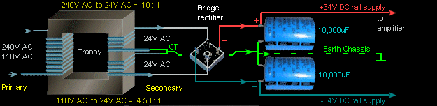
this is now my final diagram using a 25ampere diode bridge ..actually i will put it to my marshall mg15cd power supply section because of no availability of 16-o-16 center tap power transformer im gonna use a 15-0-15 transformer 6 ampere with a 25ampere diode bridge suggested by the great people here..
please check my new diagram below if it will work on my mg15 marshall amplifier power section or if my amp will work normally or gonna blow up ..
..
this is now my final diagram using a 25ampere diode bridge ..actually i will put it to my marshall mg15cd power supply section because of no availability of 16-o-16 center tap power transformer im gonna use a 15-0-15 transformer 6 ampere with a 25ampere diode bridge suggested by the great people here..
please check my new diagram below if it will work on my mg15 marshall amplifier power section or if my amp will work normally or gonna blow up
- Attachments
-
-
george giblet
- Resistor Ronker
Wired exactly like you have drawn it - it will blow up!please check my new diagram below if it will work on my mg15 marshall amplifier power section or if my amp will work normally or gonna blow up
Notice there a "+" terminal. The terminal is pointing in a different direction to all the other terminals. The "+" terminal should connect to your +V DC rail
Diagonally opposite to the "+" terminal is the "-" terminal. That should connect to your -V DC rail.
The other two terminals are the AC terminals, which are diagonally usually marked "~". or "AC" those terminals connect to the transformer.
http://copyright.lenardaudio.com/laides ... supply.gif
george giblet wrote:Wired exactly like you have drawn it - it will blow up!please check my new diagram below if it will work on my mg15 marshall amplifier power section or if my amp will work normally or gonna blow up
Notice there a "+" terminal. The terminal is pointing in a different direction to all the other terminals. The "+" terminal should connect to your +V DC rail
Diagonally opposite to the "+" terminal is the "-" terminal. That should connect to your -V DC rail.
The other two terminals are the AC terminals, which are diagonally usually marked "~". or "AC" those terminals connect to the transformer.
http://copyright.lenardaudio.com/laides ... supply.gif
ok sir thanks for the advice about the orientation of the bridge diode.. actually i will figure it out what should be the positive and negative..
if i put it right it will work sir???the whole power supply?? i compute the voltage after the big capacitor is 21 volts going to the power amp am i right ??
-
george giblet
- Resistor Ronker
Yes it should work.if i put it right it will work sir???the whole power supply?? i compute the voltage after the big capacitor is 21 volts going to the power amp am i right ??
You might get a bit more voltage, say 22V at no load. At no load the transformer output will be a little higher than 15V rms due to regulation, say 7% higher, then you lose a bit of voltage through the rectifier.
george giblet wrote:Yes it should work.if i put it right it will work sir???the whole power supply?? i compute the voltage after the big capacitor is 21 volts going to the power amp am i right ??
You might get a bit more voltage, say 22V at no load. At no load the transformer output will be a little higher than 15V rms due to regulation, say 7% higher, then you lose a bit of voltage through the rectifier.
can i mount the body of the diode bridge to the chassis of the amp?? can i put a screw on the middle hole of it and mount it to the amplifier chassis??
-
george giblet
- Resistor Ronker
No problem, a lot of people do that.can i mount the body of the diode bridge to the chassis of the amp?? can i put a screw on the middle hole of it and mount it to the amplifier chassis??
ok sir thanks..im gonna test this transformer and diode bridge..george giblet wrote:No problem, a lot of people do that.can i mount the body of the diode bridge to the chassis of the amp?? can i put a screw on the middle hole of it and mount it to the amplifier chassis??
thank you very much for the advice and opinions...