Your diode configuration doesn't make any sense. I bet two of them are in series and then parallel to the remaining diode which results in asymetric clipping.
As for your gain control: that would work the way you drew it. In your configuration it doesn't make a difference on which side the emiitor resistor is. It could be the way you sketched, or the 330R could be between ground and the pot/capacitor.
But there is at least one more alternative. In your schematic the lowend receives very little gain as it permanently sees the emittor resistor as 5,33k. To avoid this you could wire the 330R resistor straight to ground. Then connect one outer lug of the pot to the emittor and the wiper to the 100µF capacitor. Leave the other outer lug unconnected and connect the remaining capacitor side to ground. That way your gain control only affects the higher frequencies.
I hope my explanation makes some sense. This is clearly a case where a picture/schematic could have said more than a thousand words.
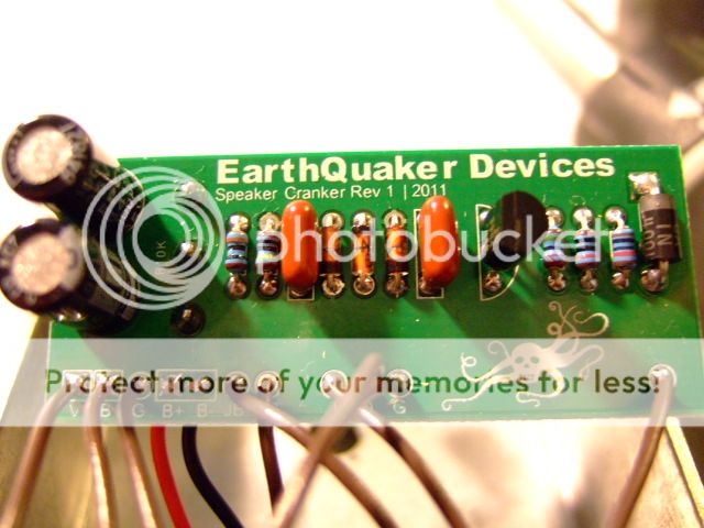
It would be great if you could have a look inside your speaker cranker to get the values of the I/O caps and the transistor type and of course confirm the gain pot assembly.
p.eat
Earthquaker Devices - Speaker Quaker [traced]
-
Motter

- Solder Soldier
Thanks for the help, p.eat
I think you're probably correct on both counts. Definitely wrt the diodes, and I'll check my Speaker Cranker when I get home tonight to verify the gain pot wiring, also the cap values and transistor type. I'm guessing it's the same 2N3904 that's in all the Electra schematics I've seen...
Also, where would one put the other diode seen in the top photo? Does that just go between +9V and ground to protect reverse polarity? What diode type would you guess it is?
BTW thanks for going easy on me, that's actually the first schematic I've ever drawn.
-
Motter
- Solder Soldier
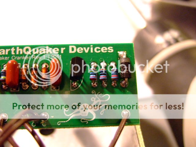
Macro mode on my camera doesn't work too well, so I didn't take any meaningful pics, but I was able to look at the other side of the board and trace the circuit.
Things look pretty much how I've drawn them above, except the noted diode error, and the cap on the collector is 68n. The volume pot and 330R are as I've drawn.
Transistor is 2N3904. I can't read the power supply diode, but it is between +9v and ground.
The resistors all measure as drawn, and as Steven posted above.
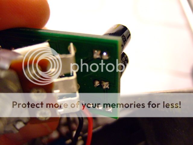
Here are some pics that might help:


-
Motter
- Solder Soldier
Thanks for the photos engineelite. I see your circuit board says rev 1/2011. Mine is rev 2/2012. Do you notice any different component values compared to what I've posted above?

-
Motter
- Solder Soldier
Inspired by IvIark, I thought I would try my hand at a vero layout:

Note the cut behind the 1N4001 on the LED+/Collector track. I'm sure this could be made a bit smaller, but it's my first attempt...
Note the cut behind the 1N4001 on the LED+/Collector track. I'm sure this could be made a bit smaller, but it's my first attempt...
Looks like your vero layout link is dead. I'd certainly be interested in giving this a go.
-
Motter
- Solder Soldier
Should be fixed now. No guarantee this works by the way, it's my first vero. I definitely recommend trying it though; it's a great overdrive with only a handful of components.
-
Motter
- Solder Soldier
Sorry, that should say "the filter cap from +9v to ground is backwards on the vero layout above." It sounds just like my storebought Speaker Cranker, but I'm going to experiment with some different transistors and clipping arrangements before I box it up. I'll post my findings here...
Hey, I built the Quaker using your vero layout and it sounds great! Never tried an original one, but I've been interested in it for a while. Thanks for the layout!
-
Motter
- Solder Soldier
Glad it worked for you. What transistor did you use by the way? I'm very curious to hear how this sounds with different transistors/clipping arrangements; it's such a simple circuit, changing these components could change the tone considerably. I used the NTE equivalents to the semiconductors in my EQD pedal, and it sounds exactly the same. Still waiting for my 1590B to arrive...
I've only had a chance to try it with the 2n3904/1n60 combo, but I hope to try other trannys and diodes this week.
-
sonicmojo
- Breadboard Brother
Nice simple design. I made one and it sounds great, mostly. I am having one small problem with noise using some 9v transformers. it is a high pitch sine wave sound. I try two identical BOSS transformers. One does it, one doesn't. Another transformer gives me a low pitched hum. It doesn't happen on battery power or with my pedal board supply either. I'm going to rebuild it since I may have a bad component or something funky with my breadboard soldering.
-
FiveseveN

- Cap Cooler
Information
This kind of circuit has very poor power supply ripple rejection so if you have a noisy or unregulated PSU it's gonna let you know.
Make sure you only use proper regulated PSUs.
Make sure you only use proper regulated PSUs.
Ignorance more frequently begets confidence than does knowledge. (Charles Darwin)
It's a funny little design. Instead of "Crackle Okay", they put a capacitor on one of the gain pot legs to quiet down the crackle to just a bit of noise. Exactly what I did when I was trying out low-hanging fruit to uncracklify Z.Vex's SHO.sonicmojo wrote:Nice simple design. I made one and it sounds great, mostly. I am having one small problem with noise using some 9v transformers. it is a high pitch sine wave sound. I try two identical BOSS transformers. One does it, one doesn't. Another transformer gives me a low pitched hum. It doesn't happen on battery power or with my pedal board supply either. I'm going to rebuild it since I may have a bad component or something funky with my breadboard soldering.
No Critcism though, I hold EQD and ZVEX high.