Hello Kaz
check the Hot Cake thread - AG did a schematic for the relay switch board, BUT, it is missing some resistor values - do you know the values?
OR, are you asking us for the values?
bajaman
Crowther Audio - Prunes & Custard
-
bajaman

- Old Solderhand
Information
- Posts: 4549
- Joined: 26 Jun 2007, 21:18
- Location: New Brighton, Christchurch, NZ
- Has thanked: 596 times
- Been thanked: 2061 times
-
theblackman

- Resistor Ronker
i think he's asking for them, i didn't realise no one had those part values, i'll check over the daughter board and post a pic.
-
bajaman
- Old Solderhand
Information
- Posts: 4549
- Joined: 26 Jun 2007, 21:18
- Location: New Brighton, Christchurch, NZ
- Has thanked: 596 times
- Been thanked: 2061 times
Thanks Richard 

bajaman
bajaman
-
krome_magnon

- Breadboard Brother
Bump...
I hope the reverse engineering of this cool effect isn't going to die!
I hope the reverse engineering of this cool effect isn't going to die!
The noise from the tape deck was only drowned out by the buzz from the wine.
-
marshmellow

- Cap Cooler
Analogguru said he has already drawn it and is only waiting for the resistor values...
-
krome_magnon
- Breadboard Brother
I just did a trace of the circuit, had a bit of a stumbling block because the pic with the yellow traces posted before has a small section of copper missing under the guitar/bass switch.
here's the amended version -

Without that small bit of copper the guitar/bass switch would have seemed to chop out half the circuit in the bass position. With it restored as per one of the other gut shots posted, it shorts out a resistor to bring a second cap fully into play to create a bigger roll off in the passive filter that comes before all the diodes.
I can't find the power supply for my scanner so I can't post my attempt at the schem. But that gives me time to tidy it up in my lunch break tomorrow before scanning and posting it tomorrow evening.
Interesting circuit and not a million miles away from the ETI Hyperfuzz, which I also have a scan of somewhere. I'll try to dig that out as well and post it at the same time.
EDIT:
Found the hyperfuzz schem -

here's the amended version -
Without that small bit of copper the guitar/bass switch would have seemed to chop out half the circuit in the bass position. With it restored as per one of the other gut shots posted, it shorts out a resistor to bring a second cap fully into play to create a bigger roll off in the passive filter that comes before all the diodes.
I can't find the power supply for my scanner so I can't post my attempt at the schem. But that gives me time to tidy it up in my lunch break tomorrow before scanning and posting it tomorrow evening.
Interesting circuit and not a million miles away from the ETI Hyperfuzz, which I also have a scan of somewhere. I'll try to dig that out as well and post it at the same time.
EDIT:
Found the hyperfuzz schem -
The noise from the tape deck was only drowned out by the buzz from the wine.
Shame you didn't post that earlier I just took ages looking for that 
Here's what I got, see how it matches up https://i199.photobucket.com/albums/aa1 ... crusty.jpg
Here's what I got, see how it matches up https://i199.photobucket.com/albums/aa1 ... crusty.jpg
-
krome_magnon
- Breadboard Brother
Close, though I have the whole mess of diodes etc. a little differently. The amended trace should go like...Jim777 wrote:Shame you didn't post that earlier I just took ages looking for that
Here's what I got, see how it matches up https://i199.photobucket.com/albums/aa1 ... crusty.jpg

Which, as I said above, makes a lot more sense as it modifies that resistor & cap filter at the start of the diode chain to roll off more highs in the bass mode by shorting out the 100k resistor and bringing the 220n fully into play.
The noise from the tape deck was only drowned out by the buzz from the wine.
-
krome_magnon
- Breadboard Brother
My trace from last night... 
I think I included everything.
I think I included everything.
The noise from the tape deck was only drowned out by the buzz from the wine.
Well mine looks a bit confusing the way I've drawn those diodes
I checked it again and it looks ok to me but doesn't look like what you drew. Maybe you could put some resistor values in there? I've never heard one of these do they sound any good?
I checked it again and it looks ok to me but doesn't look like what you drew. Maybe you could put some resistor values in there? I've never heard one of these do they sound any good?
-
krome_magnon
- Breadboard Brother
Mine redone much in a much more tidy way. Still unsure of resistor values, either my eyes are going or my monitor is crap, but I can hardly tell what some of the resistor colour bands are on the gut shots.

The noise from the tape deck was only drowned out by the buzz from the wine.
-
krome_magnon
- Breadboard Brother
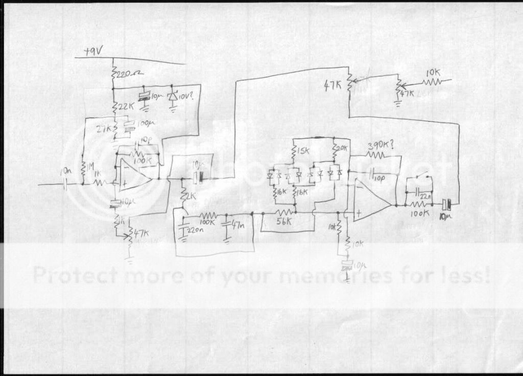
latest version, with best guess values at most components.

The noise from the tape deck was only drowned out by the buzz from the wine.
-
RLBJR65

- Resistor Ronker
Information
Great job! Here is the pic theblackman posted I marked the resistors that were not marked as I read them. Couple are tough like the 39 or 390K
looks like a couple of those bands could be smudges. IMO it's probably 390K.
https://img526.imageshack.us/my.php?ima ... ersli3.jpg
looks like a couple of those bands could be smudges. IMO it's probably 390K.
https://img526.imageshack.us/my.php?ima ... ersli3.jpg
-
krome_magnon
- Breadboard Brother
Here's my trace compared to the gutshot. A few values adjusted and I'll further tweak the values as per RLBJR65's posting.

The noise from the tape deck was only drowned out by the buzz from the wine.
-
Torchy
Information
Why would you put a 10V zener on a 9V supply ? Protection against a higher output psu connected by mistake ?
-
krome_magnon
- Breadboard Brother
Hence the question mark...Torchy wrote:Why would you put a 10V zener on a 9V supply ? Protection against a higher output psu connected by mistake ?
The noise from the tape deck was only drowned out by the buzz from the wine.